
Method and Apparatus for Forming an Ink Pattern Exhibiting a Two-Dimensional Ink Gradient

a two-dimensional ink gradient and ink pattern technology, applied in the direction of rotary inkjet printing press, rotary lithographic machine, printing, etc., can solve the problems of large space occupation and difficult installation in a compact manner in the inking system of the printing press, so as to improve the uniformity of ink distribution, increase the distance over which ink can be distributed, and increase the oscillation amplitude

Inactive Publication Date: 2010-04-15
KBA NOTASYS SA
View PDF10 Cites 12 Cited by
  • Summary
  • Abstract
  • Description
  • Claims
  • Application Information

AI Technical Summary

Benefits of technology

[0011]In particular, an aim of the present invention is to provide a solution that enables an increase of the distance over which the ink can be distributed without this necessitating an increase of the oscillation amplitude of the chablon cylinder used to distribute the ink.
[0012]Still another aim of the present invention is to provide a solution that helps improving the uniformity of the distribution of ink in the axial and circumferential directions.
[0013]A further aim of the present invention is to provide a solution that enables the design of a compact inking apparatus.
[0015]According to the invention, at least first and second chablon cylinders are placed one after the other along an inking path of the ink train inking the form cylinder for distributing ink in the axial and circumferential directions, which first and second chablon cylinders are subjected to cyclical oscillation movements in the axial direction and the circumferential direction. Thanks to this solution, and as discussed hereinafter in greater detail, one can achieve a better and more uniform distribution of ink along the axial and circumferential directions. One can furthermore achieve distribution of ink over a distance that is comparatively greater than with the prior art solution.

Problems solved by technology

The solution of patent RU 2 147 282 C1 accordingly requires a substantial amount of space and is therefore difficult to install in a compact manner in the inking system of a printing press.

Method used


Image

  • Method and Apparatus for Forming an Ink Pattern Exhibiting a Two-Dimensional Ink Gradient
  • Method and Apparatus for Forming an Ink Pattern Exhibiting a Two-Dimensional Ink Gradient
  • Method and Apparatus for Forming an Ink Pattern Exhibiting a Two-Dimensional Ink Gradient

Examples


Embodiment Construction

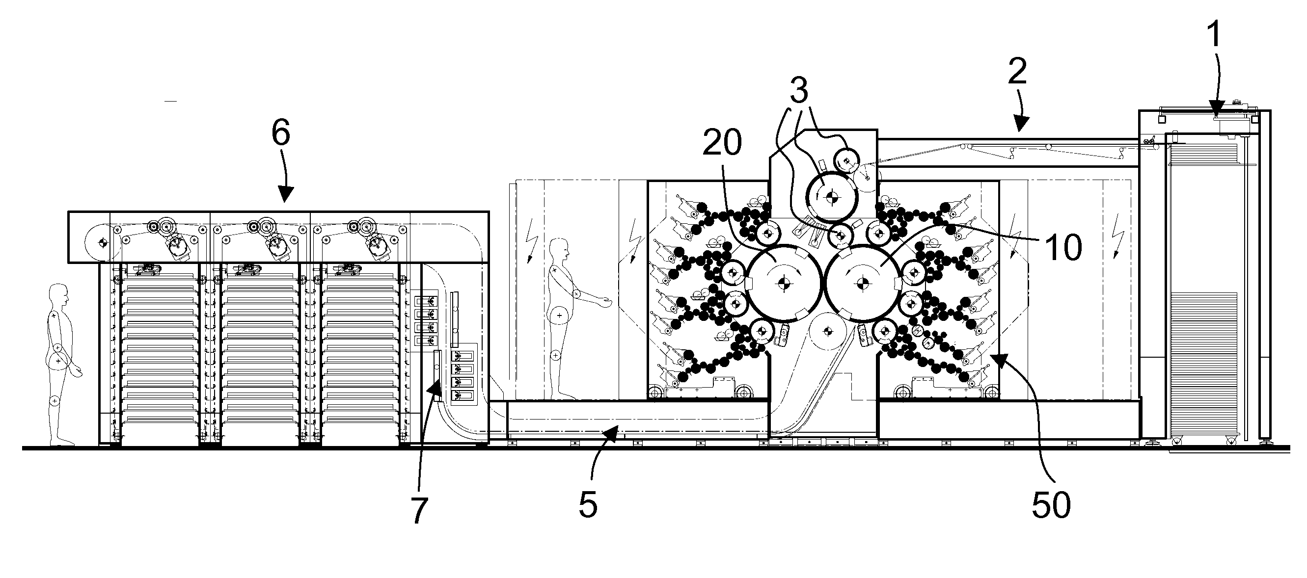
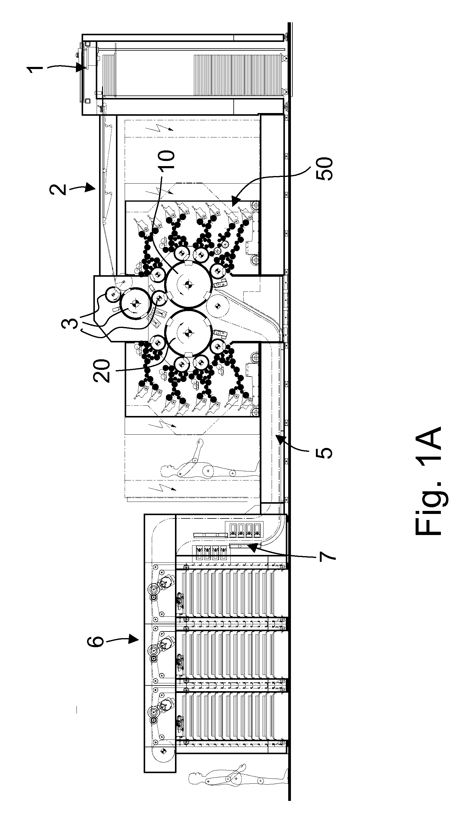
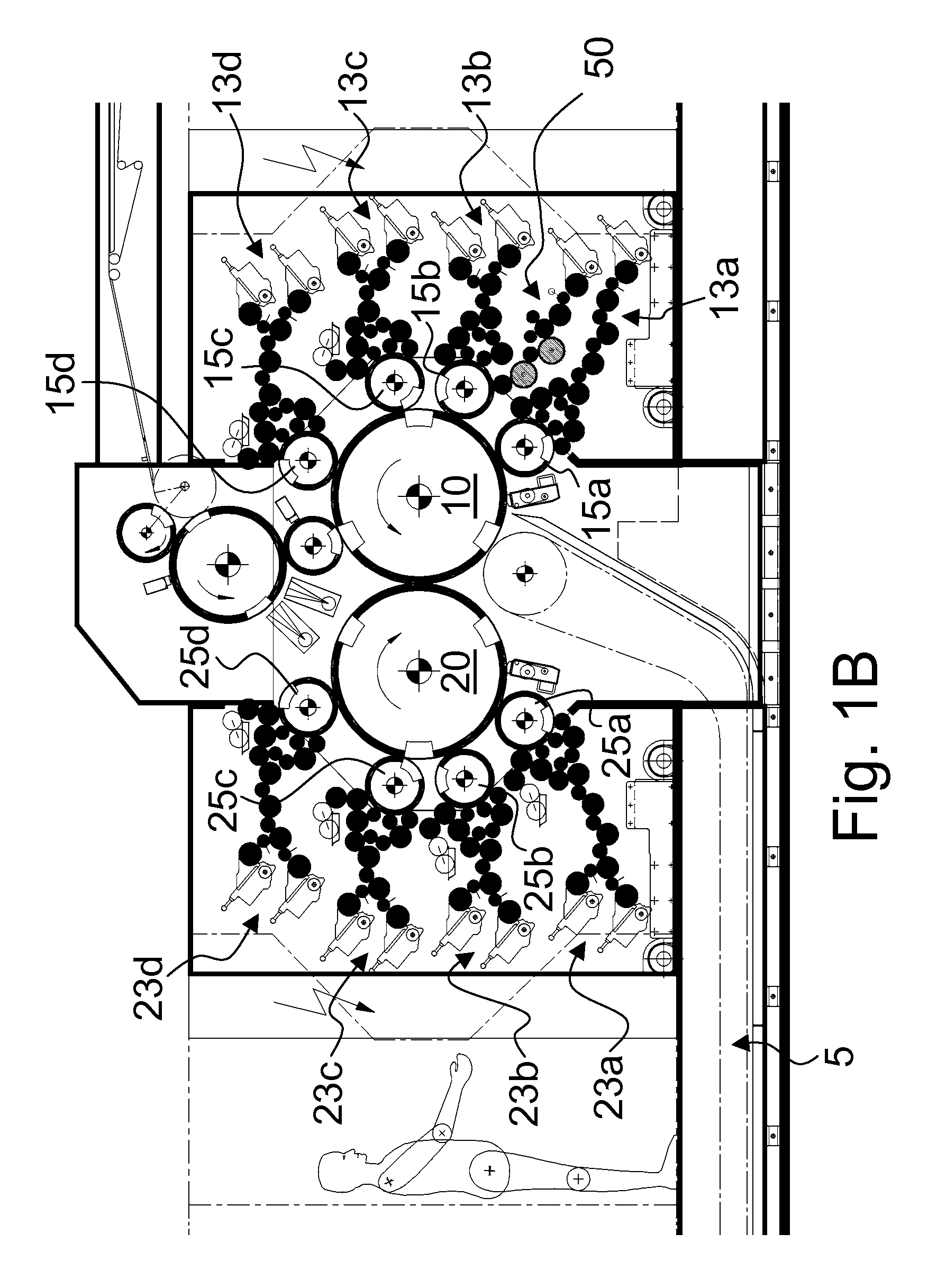
[0030]The invention will be described hereinafter in the context of a sheet-fed offset printing press for printing security papers, in particular banknotes. As this will be apparent from the following, the illustrated printing press comprises a printing group adapted for simultaneous recto-verso offset printing of the sheets. This printing group is as such similar to that described in European patent application EP 0 949 069 which is incorporated herein by reference. It shall however be appreciated that the present invention could be applied in any other type of printing press wherein a ink pattern is to be applied on the surface of a form cylinder. Furthermore, while the following discussion will focus on the printing of sheets, the invention is equally applicable to the printing on a continuous web of material.

[0031]FIGS. 1A, 1B and 1C are side views of a sheet-fed offset printing press equipped with an inking apparatus according to one embodiment of the invention. The printing gr...


PUM


Abstract

There is described a method and an inking apparatus (50) for forming an ink pattern (80) on the surface of a form cylinder (15b) of a printing press, which ink pattern (80) exhibits, at least in part, a two-dimensional ink gradient extending in an axial direction and a circumferential direction on the surface of the form cylinder (15b). At least first and second chablon cylinders (20, 25) are placed one after the other along an inking path of the ink train (20, 25, 30, 31, 32, 33, 34, 35a, 35b, 36, 37) inking the form cylinder (15b) for distributing ink in the axial and circumferential directions and means (200, 201, 210, 211, 212, 250, 251, 260, 261, 262) are provided for subjecting the first and second chablon cylinders (20, 25) to cyclical oscillation movements in the axial direction and the circumferential direction.

Description

TECHNICAL FIELD[0001]The present invention generally relates to a method and an apparatus for forming an ink pattern on the surface of a form cylinder of a printing press, which ink pattern exhibits, at least in part, a two-dimensional ink gradient extending in an axial direction and a circumferential direction on the surface of the form cylinder. The present invention is in particular applicable in the context of the production of security documents, such as banknotes, passports, ID documents, checks or the like securities.BACKGROUND OF THE INVENTION[0002]Forming an ink pattern on the surface of a form cylinder of a printing press, which ink pattern exhibits, at least in part, a two-dimensional ink gradient extending in an axial direction and a circumferential direction on the surface of the form cylinder is known as such in the art. This principle was recently developed by Russian entity Goznak and is exploited in the context of so-called two-dimensional iris printing (hereinafter...

Claims


Application Information

Patent Timeline
Patent Type & Authority Applications(United States)
IPC IPC(8): B41F9/02B41M1/10
CPCB41F7/02B41F7/08B41F9/021B41P2200/13B41F31/00B41F31/15B41F11/02
Inventor SCHWITZKY, VOLKMAR ROLF
Owner KBA NOTASYS SA
Learn More