
Cover for Portable Electronic Device

a technology for electronic devices and covers, applied in the directions of portable computer details, instruments, transportation and packaging, etc., can solve the problem that the surface of portable electronic devices is relatively easy to be damaged

Inactive Publication Date: 2010-04-01
APPLE INC
View PDF29 Cites 312 Cited by
  • Summary
  • Abstract
  • Description
  • Claims
  • Application Information

AI Technical Summary

Benefits of technology

[0012]As an integrated electrical skin, one embodiment can, for example, include at least a compliant body including an cavity for receiving an electronic device, and one or more electrical components being at least partially disposed within the compl...

Problems solved by technology

Typically, the surfaces of portable electronic devices are relatively easily damaged such as by scratches, dents and the like.

Method used


Image

  • Cover for Portable Electronic Device
  • Cover for Portable Electronic Device
  • Cover for Portable Electronic Device

Examples


Embodiment Construction

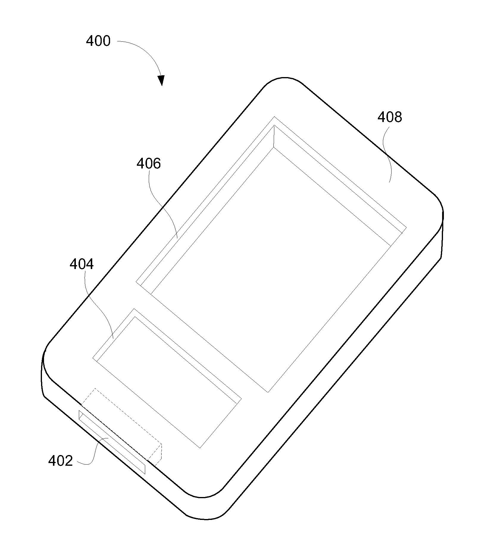
[0041]The invention pertains to a cover for a portable electronic device. The cover can include at least one electrical component. For example, in one embodiment, an electrical component can be embedded in the cover. When the cover is placed on or mated with the portable electronic device, the electrical component embedded in the cover is able to interact with electrical circuitry of the portable electronic device. Advantageously, the cover can not only provide a protective and / or ornamental covering for the portable electronic device but can also augment the electrical capabilities of the portable electronic device. The invention is particularly well suited for portable, battery-powered electronic devices, and more particularly handheld battery-powered electronic devices. Examples of portable, battery-powered electronic devices can include laptops, tablet computers, media players, phones, GPS units, remote controls, personal digital assistant (PDAs), and the like.

[0042]A cover for ...


PUM

PropertyMeasurementUnit
Flexibilityaaaaaaaaaa
Moldableaaaaaaaaaa

Abstract

A cover for a portable electronic device is disclosed. The cover can include at least one electrical component. For example, in one embodiment, an electrical component can be embedded in the cover. When the cover is placed on or mated with the portable electronic device, the electrical component embedded in the cover is able to interact with electrical circuitry of the portable electronic device. Advantageously, the cover can not only provide a protective and / or ornamental covering for the portable electronic device but can also augment the electrical capabilities of the portable electronic device.

Description

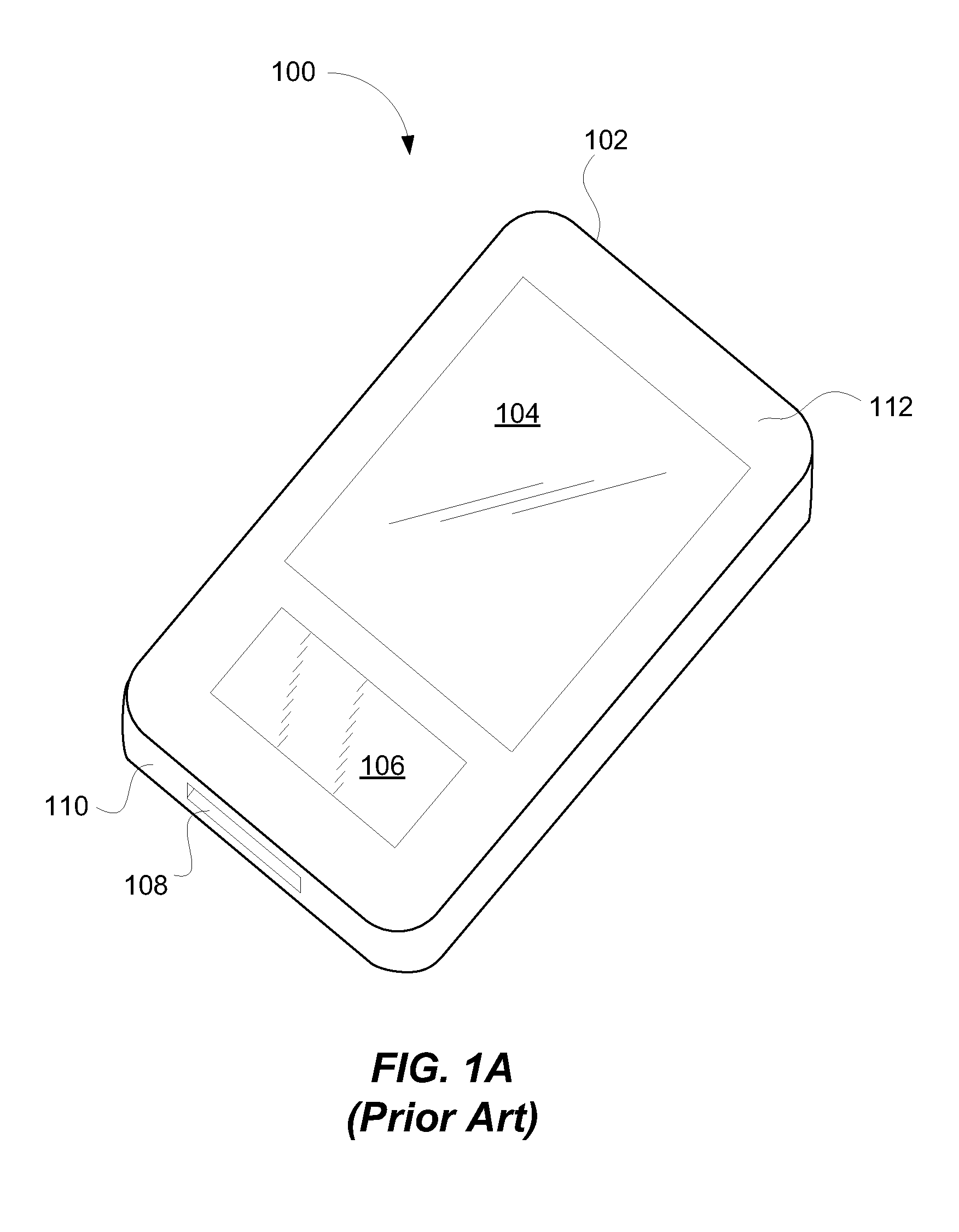
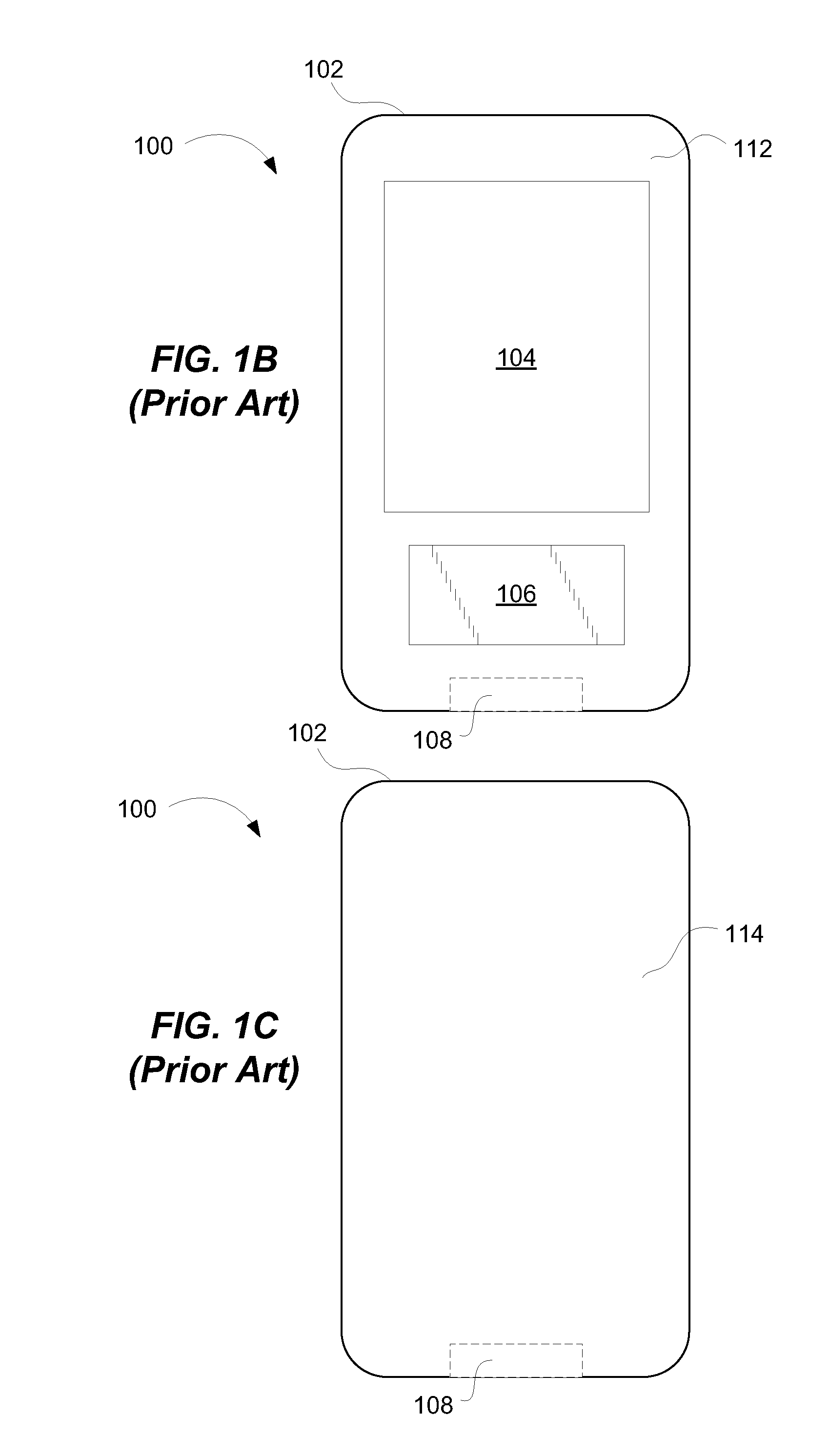
CROSS-REFERENCE TO RELATED APPLICATION[0001]This application claims priority to U.S. Provisional Patent Application No. 61 / 101,623, filed Sep. 30, 2008, entitled “COVER FOR PORTABLE ELECTRONIC DEVICE,” which is herein incorporated by reference.BACKGROUND OF THE INVENTION[0002]Portable electronic devices are commonplace today. Some examples of portable electronic devices include portable digital assistants, portable media players, mobile telephones, and portable game players.[0003]FIGS. 1A-1C are diagrammatic illustrations of a conventional portable electronic device 100. More specifically, FIG. 1A is a perspective view of the portable electronic device 100, FIG. 1B is a front view of the portable electronic device 100, and FIG. 1C is a back view of the portable electronic device 100. The portable electronic device 100 includes a housing 102 that forms an external surface of the portable electronic device 100. The housing 102 supports a display 104 and a user input region 106. The di...

Claims


Application Information

Patent Timeline
IPC IPC(8): B65D85/00B29C45/14
CPCB29C45/14639Y10T29/49018G06F1/1632G06F1/1626G06F2203/04809G06F3/0393G06F3/041G06F3/0416G06F1/1669G06F1/169
Inventor HOELLWARTH, QUIN C.ALTEN, BRETT GREGORY
Owner APPLE INC
Learn More