Eureka AIR delivers breakthrough ideas for toughest innovation challenges, trusted by R&D personnel around the world.

Projection system and expansion module

Inactive Publication Date: 2010-03-25
CORETRONIC
View PDF10 Cites 11 Cited by
  • Summary
  • Abstract
  • Description
  • Claims
  • Application Information

AI Technical Summary

Benefits of technology

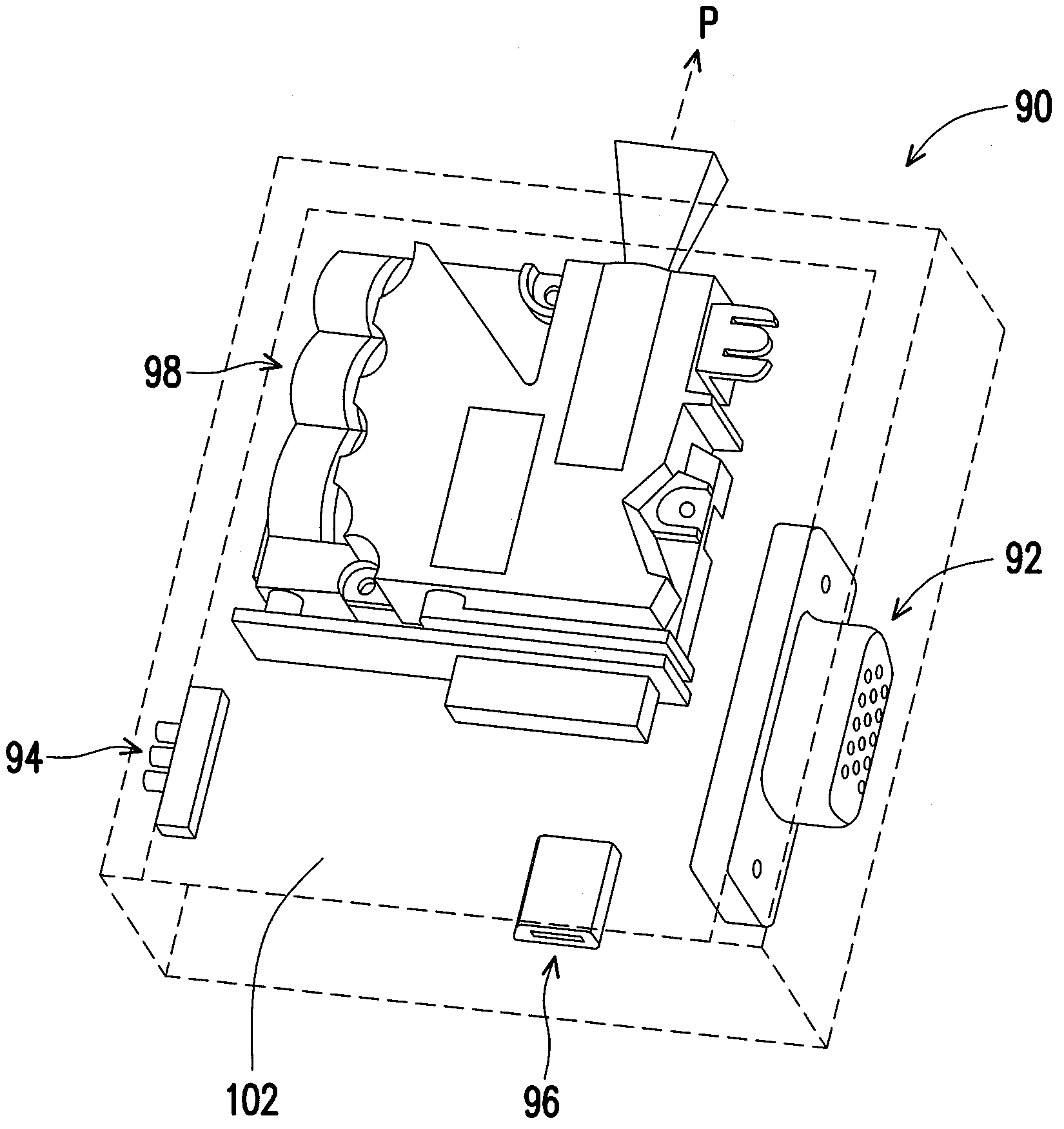
[0010]The present invention is directed to a projection system and an expansion module adapted to a projector. The projection system includes a projector and an expansion module. The expansion module is fixed to the projector in a pluggable manner via an output port of the expansion module, so as to expand the function of the projector and improve the practicability thereof.
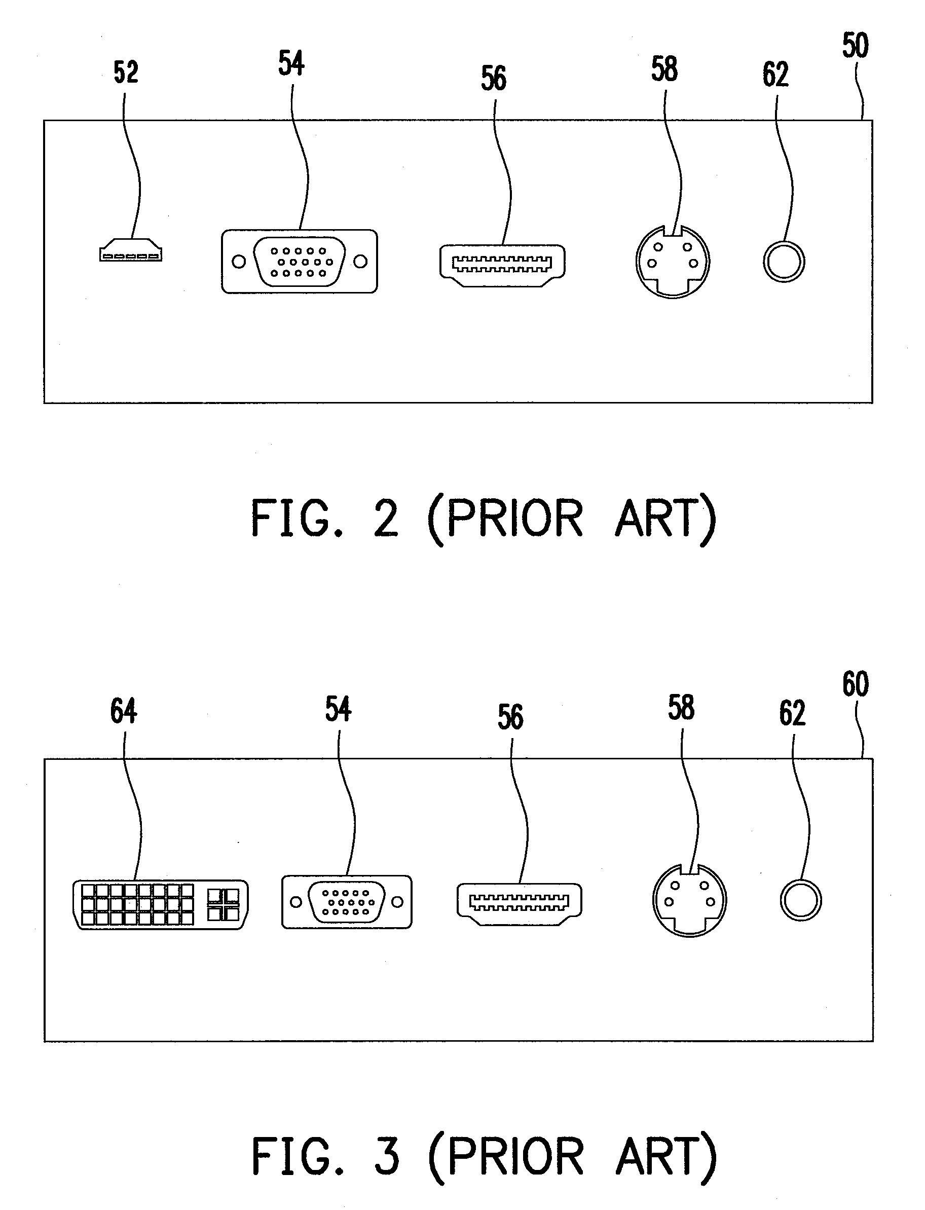
[0020]In the embodiments of the present invention, the user may select an expansion module having a suitable video input interface according to the video output interface of the video device, and connect the expansion module to the projector. Therefore, the projector may be connected with different video output interfaces according to the demands of the user, so as to improve the practicability of the projector.
[0021]In the embodiments of the present invention, when the expansion module is fixed on one side of the projector in a pluggable manner via the output port thereof, the expansion module and the projector may be connected without any additional cable, such that both the overall appearance and portability are improved.

Problems solved by technology

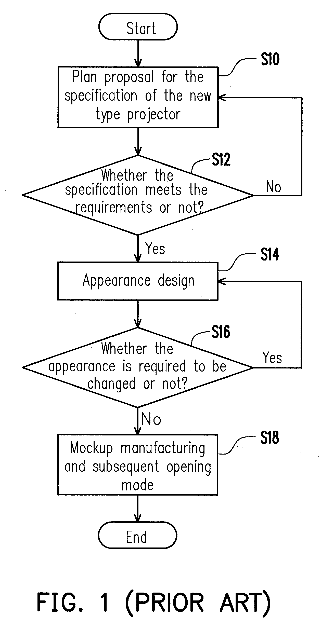
However, after opening mode, if the specification or the appearance design of the projector is required to be changed, an expensive cost should be paid for making the mechanism mold again, so as to be undoubtedly a cost burden for the manufacturer, and reduce the will to change the design.
Therefore, when being attracted by the appearance of the projector, if the projector does not provide an interface suitable for the consumer's own input / output specification, the consumer may give up the ideal projector to choose the projector with other appearances.
However, the expected sale purpose may not be achieved in such a case for manufacturers who take special appearance or series appearance as the main marketing tactics.

Method used


Image

  • Projection system and expansion module
  • Projection system and expansion module
  • Projection system and expansion module

Examples


Embodiment Construction

[0035]In the following detailed description of the preferred embodiments, reference is made to the accompanying drawings which form a part hereof, and in which are shown by way of illustration specific embodiments in which the invention may be practiced. In this regard, directional terminology, such as “top,”“bottom,”“front,”“back,” etc., is used with reference to the orientation of the Figure(s) being described. The components of the present invention can be positioned in a number of different orientations. As such, the directional terminology is used for purposes of illustration and is in no way limiting. On the other hand, the drawings are only schematic and the sizes of components may be exaggerated for clarity. It is to be understood that other embodiments may be utilized and structural changes may be made without departing from the scope of the present invention. Also, it is to be understood that the phraseology and terminology used herein are for the purpose of description an...


PUM


Abstract

A projection system and an expansion module adapted to a projector are provided. The projection system includes a projector and an expansion module. The expansion module includes a housing, a logic circuit, and an output port. The logic circuit is disposed in the housing to control an operation of the expansion module. The output port is disposed in the housing and coupled to the logic circuit. The output port is connected to an input port of the projector and outputs a data stream to the input port, such that the projector generates an image and projects the image according to the data stream.

Description

CROSS-REFERENCE TO RELATED APPLICATION[0001]This application claims the priority benefit of Taiwan application serial no. 97136350, filed on Sep. 22, 2008. The entirety of the above-mentioned patent application is hereby incorporated by reference herein and made a part of specification.BACKGROUND OF THE INVENTION[0002]1. Field of the Invention[0003]The present invention generally relates to an expansion module, in particular, to a projection system and an expansion module adapted to a projector.[0004]2. Description of Related Art[0005]Projection devices may project an image onto a large screen to facilitate more people to watch the content displayed on the screen at the same time, and projection devices are applied in public, such as in companies and schools. Further, with the trend that home display products are developed towards the direction of large size, projection devices are gradually popularized in common families, and become a common electronic product in modern life.[0006]...

Claims


Application Information

Patent Timeline
IPC IPC(8): H04N5/64
CPCH04N9/641H04N9/3173
Inventor CHIEN, WEN-CHANGLEE, HUNG-LINYIN, NAN-JIUNFAN CHIANG, CHIH-HENGWANG, CHUN-PING
Owner CORETRONIC
Why Eureka
Eureka Blog
Learn More