Image reading apparatus and method to correct images

a technology of image reading and image, which is applied in the direction of electrical equipment, instruments, computing, etc., can solve the problems of large number of light receiving elements to be used to read images, and large number of light receiving elements, so as to reduce image reproducibility and image quality.

Active Publication Date: 2010-03-04
BROTHER KOGYO KK
View PDF20 Cites 4 Cited by
  • Summary
  • Abstract
  • Description
  • Claims
  • Application Information

AI Technical Summary

Benefits of technology

[0009]In general, unevenness of the pixel data output from a plurality of light receiving elements equipped within a sensor unit is relatively smaller than unevenness of the pixel data output from a plurality of light receiving elements equipped in different sensor units. Therefore, the pixel data output from the light receiving elements equipped within a sensor unit may be corrected based on a same piece of correcting information in the shading correction data without lowering a quality of reproducibility of the image. Thus, the pixel data can be corrected based on a smaller number of pieces of correcting information of the shading correction data than the number of the light receiving element to be used to read the image. Because the number of pieces of correcting information in the first shading correction data is smaller than the number of light receiving elements to be used to read the image, according to the above configuration, a volume to store the first shading correction data can be downsized without lowering the quality of reproducibility of the image.

Problems solved by technology

However, the number of light receiving elements equipped to an image sensor is generally large.
Therefore, inherently, the number of light receiving elements to be use to read an image is large.

Method used


Image

  • Image reading apparatus and method to correct images
  • Image reading apparatus and method to correct images
  • Image reading apparatus and method to correct images

Examples


Embodiment Construction

[0017]Hereinafter, a first embodiment according to an aspect of the present invention will be described with reference to the accompanying drawings.

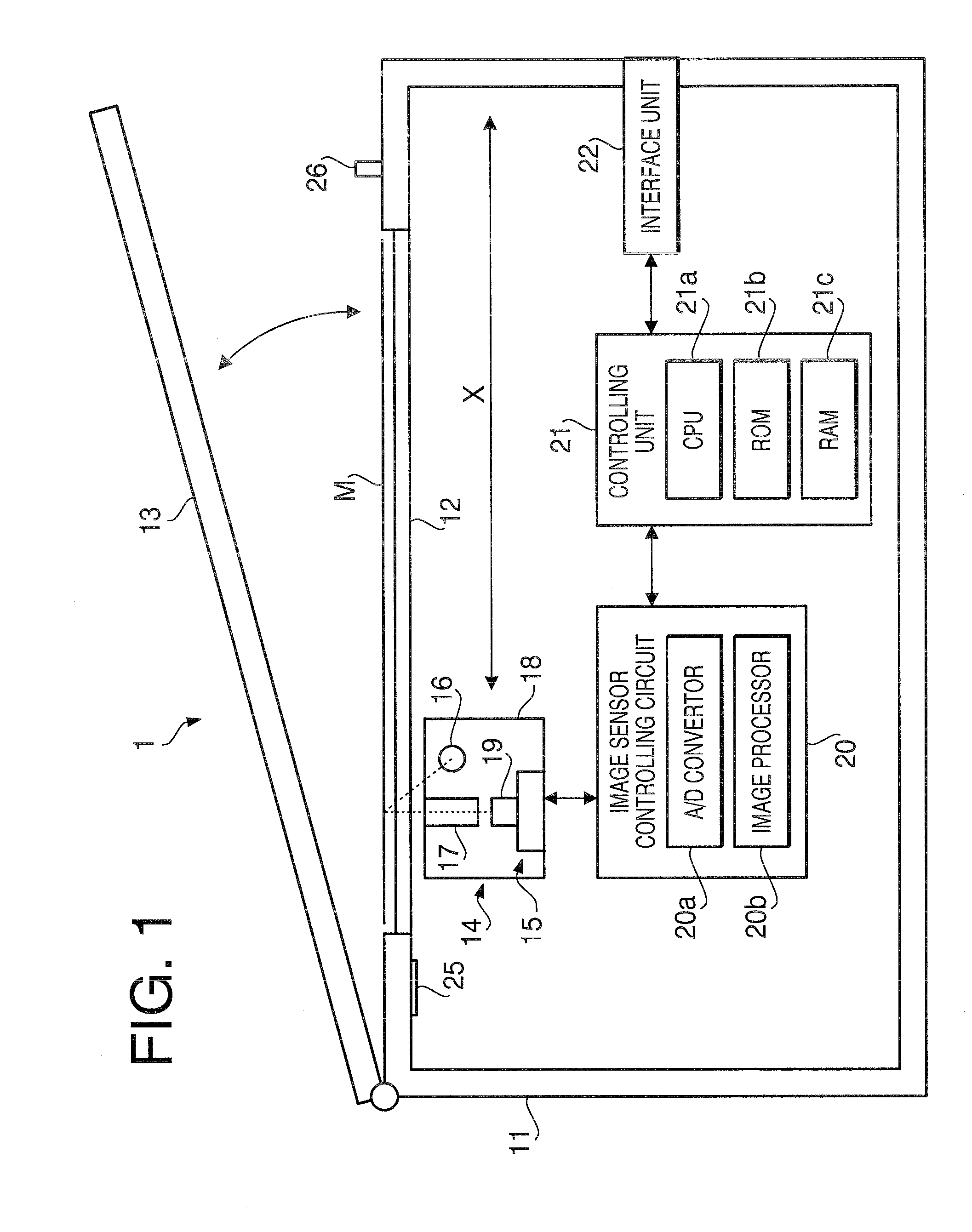
[0018]Firstly, an overall configuration of an image scanner 1 according to the embodiment of the present invention will be described. FIG. 1 is a block diagram to illustrate an image scanner 1 according to an embodiment of the present invention. The image scanner 1 is a flatbed-typed image reading apparatus which reads an original image formed on a document M being placed on a platen glass 12 in CIS (contact image sensing) method.

[0019]The image scanner 1 has a chassis 11, which is formed to have a box-like shape. The platen glass 12, on which the document M having the original image is placed to be read, is provided on top of the chassis 11. The platen glass 12 is a sheet of transparent glass, and the document M, e.g., a printed document, a photograph, or pages of a book, is placed thereon to be read. The image scanner 1 further include...


PUM


Abstract

An image reading apparatus to read an image and generate pixel data representing the image is provided. The image reading apparatus includes an image sensor having a plurality of sensor units, each of which includes a plurality of light receiving elements, a data storage store shading correction data, which is used to correct unevenness caused in the pixel data, including first shading correction data, and a data corrector to correct the pixel data output from the light receiving elements based on the shading correction data. The data corrector corrects the pixel data based on the first shading correction data when a number of light receiving elements used to read the image in each sensor unit is greater than a number of pieces of correcting information in the first shading correction data.

Description

CROSS REFERENCE TO RELATED APPLICATION [0001]This application claims priority from Japanese Patent Application No. 2008-218795, filed on Aug. 27, 2008, the entire subject matter of which is incorporated herein by reference.BACKGROUND [0002]1. Technical Field[0003]An aspect of the present invention relates to an image reading apparatus and a method to correct the read images.[0004]2. Related Art[0005]Image reading apparatus to read images and reproduce the read images have been used, and some image reading apparatuses are capable of correcting values of pixel data, which is obtained from light receiving elements of an image sensor, based on white level correction data (hereinafter also referred to as shading correction data), for improved reproducibility. Such an image reading apparatus is disclosed in, for example, Japanese Patent Provisional Publication No. 2008-85600. According to the disclosure, the shading correction data is a collection of pieces of correcting information, and ...

Claims


Application Information

Patent Timeline
Patent Type & Authority Applications(United States)
IPC IPC(8): H04N1/04
CPCH04N1/1017H04N1/193H04N2201/0081H04N1/4076H04N1/401
Inventor NAGASAKA, HIDEAKI
Owner BROTHER KOGYO KK
Why Eureka
Try Eureka