
Direct solve image based wave-front sensing

a wave-front sensing and image technology, applied in the field of space-based imaging, can solve the problems of degrading the image wave-front, requiring an unacceptably large number of iterations to converge, and requiring a computationally intensive process. to achieve the effect of simplifying the control of articulated mirrors and reducing the wave-front sensing and control tim

Inactive Publication Date: 2010-03-04
NASA
View PDF0 Cites 16 Cited by
  • Summary
  • Abstract
  • Description
  • Claims
  • Application Information

AI Technical Summary

Benefits of technology

[0012]It is yet another aspect of the invention to minimize the wave-front sensing and control time required to align and simplify control of articulated mirrors in an array of mirrors used in an interferometric imaging system.

Problems solved by technology

Misaligning the mirrors degrades the image wave-front, blurring or aberating images.
Misalignment can even cause multiple images, with severe misalignment causing one per aperture or telescope.
Even with such precise control, correctly aligning a number of articulated mirrors with each other can be a long, exhausting, iterative process.
Previously, this was a computationally intensive process that required an unacceptably high number of iterations to converge.

Method used


Image

  • Direct solve image based wave-front sensing
  • Direct solve image based wave-front sensing
  • Direct solve image based wave-front sensing

Examples


Embodiment Construction

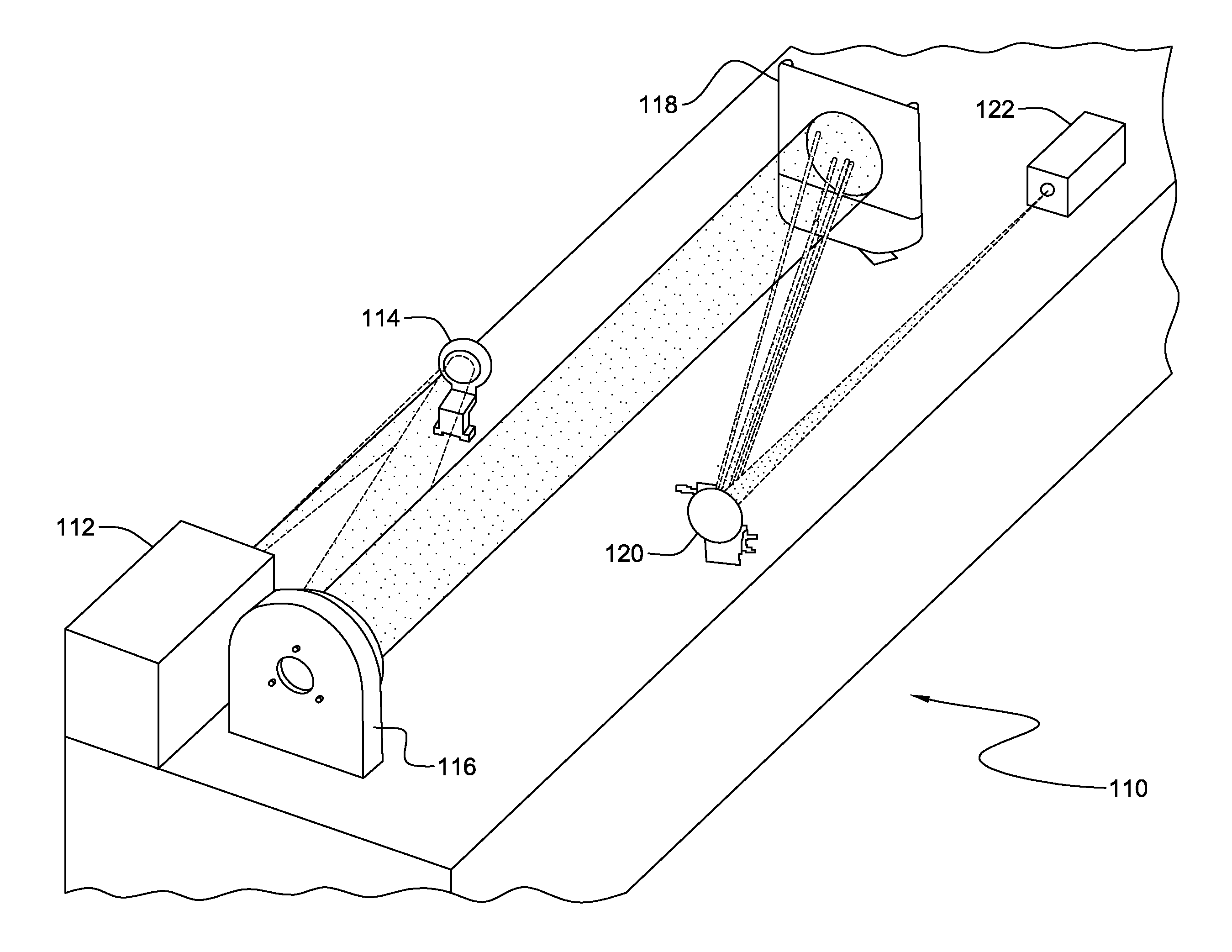
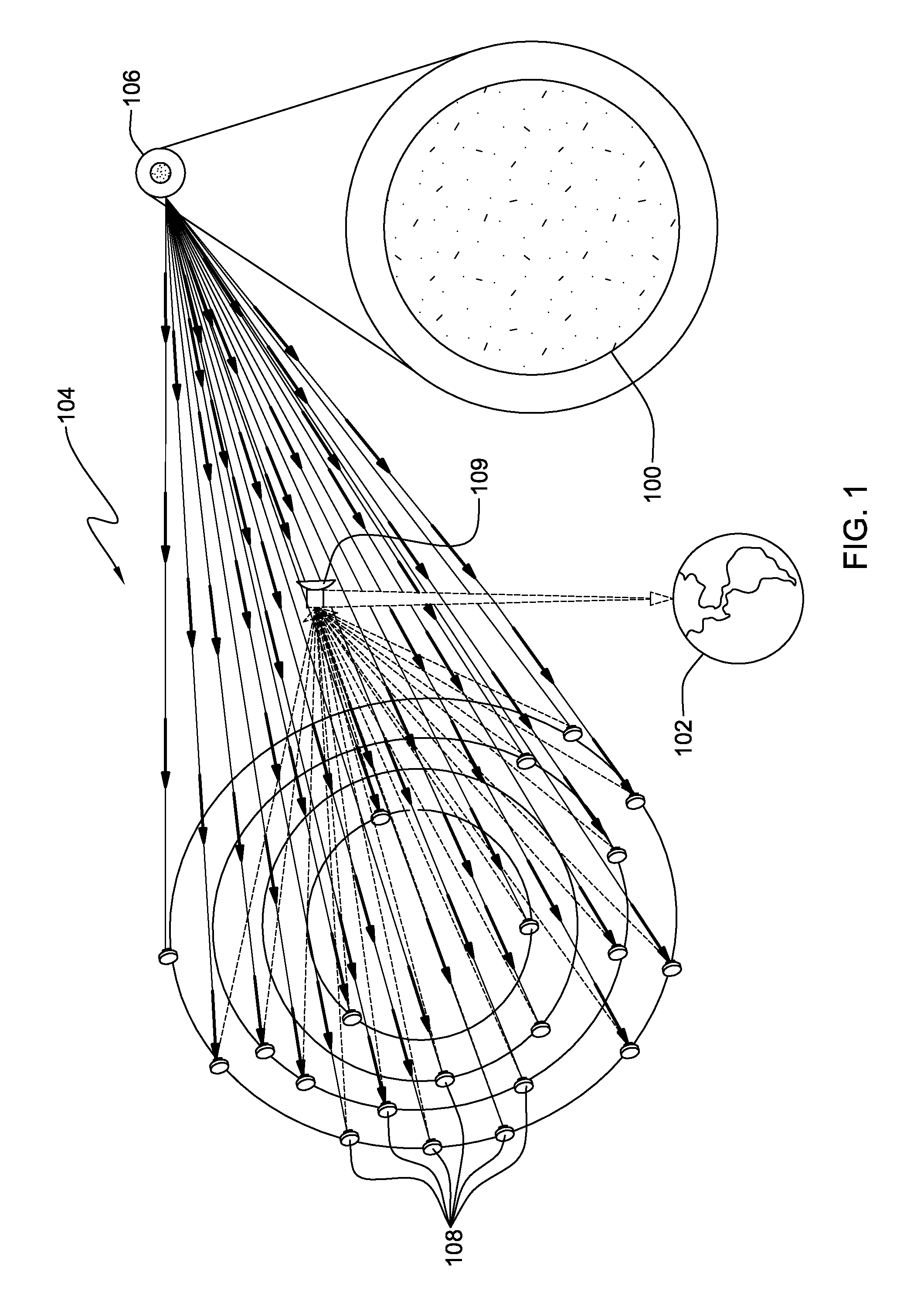
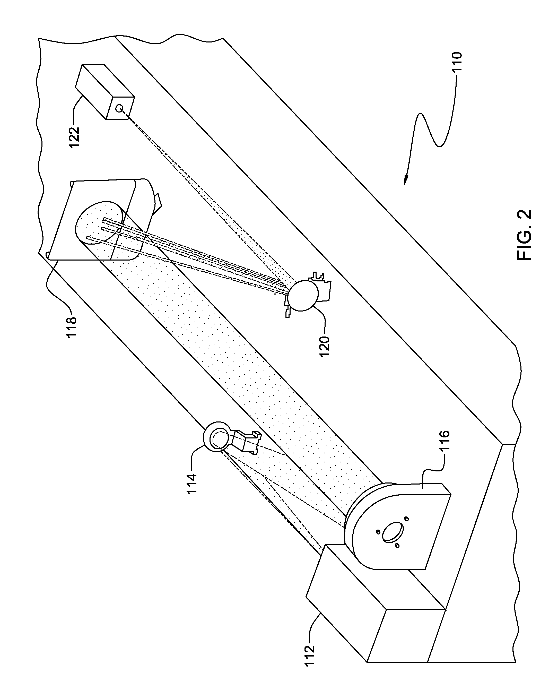
[0023]Turning now to the drawings and more particularly FIG. 1 shows an example of a National Aeronautics and Space Administration (NASA) space-based imaging interferometer, e.g., the NASA Stellar Imager (SI). In this example, application of the present invention provides remote onboard wave-front sensing and control to maintain aperture alignment during science observations and after array reconfigurations. SI is an ultraviolet (UV) optical interferometry mission in the NASA Sun-Earth 100, 102 connection, far-horizon roadmap. Such a mission requires both spatial and temporal resolution of stellar magnetic activity patterns 104, representing a broad range of activity level from stars 106. Studying these magnetic activity patterns 104 enables improved forecasting of solar / stellar magnetic activity as well as an improved understanding of the impact of that magnetic activity on planetary climate and astrobiology. SI, for example, may also allow for measuring internal structure and rota...


PUM


Abstract

A method of aligning an array of mirrors and computer program product therefor. The method may be used to align mirrors in a sparse aperture telescope system, e.g., a spaced based imaging interferometer. An image projected onto mirrors in an array of mirrors is reflected onto a sensor, where a point spread function (PSF) is collected from a pair of mirrors. A spatial image is extracted from PSF sidebands and a difference (e.g., piston difference) is determined for the pair of mirrors from the spatial image. Tip and tilt are determined for the pair of mirrors from spatial image characteristics.

Description

RELATED CASES[0001]This application is a continuation in-part application and claims the benefit of U.S. NonProvisional application Ser. No. 12 / 198,466, filed Aug. 26, 2008.[0002]The invention described herein was made by an employee of the United States Government, and may be manufactured and used by or for the Government for governmental purposes without the payment of any royalties thereon or therefor.BACKGROUND OF THE INVENTION[0003]1. Field of the Invention[0004]The present invention is generally related to space-based imaging and more particularly to accurately sensing and controlling the wave-front in a space-based imaging interferometer.[0005]2. Background Description[0006]National Aeronautics and Space Administration (NASA) has been developing interferometric space-based imaging to realize future larger aperture science missions. Imaging interferometers contain an array of two (2) or more telescopes, or apertures, that coherently mix (interferometrically combine) images in ...

Claims


Application Information

Patent Timeline
Patent Type & Authority Applications(United States)
IPC IPC(8): G01B11/02
CPCG01B11/272
Inventor LYON, RICHARD G.
Owner NASA
Learn More