Bucking coil and b-field measurement system and apparatus for time domain electromagnetic measurements

a technology of time domain electromagnetic measurement and bucking coil, which is applied in the field of geophysical electromagnetic measurements, can solve the problems of affecting the accuracy of existing systems, difficulty in acquiring data over the entire period of a concentric dipole htem system, and loss of spatial resolution, so as to eliminate pre-amplifier set-off and temperature-dependent drift

Active Publication Date: 2010-03-04
GEOTECH
View PDF8 Cites 21 Cited by
  • Summary
  • Abstract
  • Description
  • Claims
  • Application Information

AI Technical Summary

Benefits of technology

[0020]In yet another aspect, the present disclosure relates to a signal processing method to produce a B-field measurement comprising: obtaining a receiver coil signal from a receiver coil positioned within a bucking coil which is further positioned within a transmitter coil, each coil being positioned in substantially concentric orientation relative to the others and being electrically connected with one another to produce the receiver coil signal; continuously digitizing the receiver coil signal by way of a ADC that filters the signal; obtaining the digitized signal by a signal processing means unit; eliminating pre-amplifier set-off and temperature-dependent drifts by averaging the signal at a given point of a waveform point-by-point over a set of periods; averaging the waveform over one or more positive and negative semi-periods or signals to obtain an off-set signal; optionally subtracting a resulting digital signal from each point; integrating the digital signal over at least one entire period so as to produce the B-field measurement; and binning the digital signal into gates with substantially equal time intervals in a logarithmic scale.

Problems solved by technology

However, this system does not determine the B-field, but merely outputs the dB / dt signal at the receiver coil during part of the transmitter coil on-time, in addition to the standard off-time measurement.
The prior art generally experiences problems affecting the accuracy of existing systems.
For example, acquiring data over the entire period in a concentric dipole HTEM system can be challenging since the signal during the on-period is typically many orders of magnitude higher than during the off-period.
However, the separation imposed by the large distance introduces negative characteristics such as loss of spatial resolution or a system that is unwieldy and difficult to tow in flight, especially by helicopter.
Existing prior art that uses a bucking coil is generally restricted to EM measurements in the frequency-domain and has not been implemented for measurement in time-domain.
The prior art encounters multiple problems such as, for example, structural vibrations of the coils produced during flight by wind buffeting or aircraft machinery, resulting in spurious signals at the receiver coil with a wide frequency spectrum.

Method used


Image

  • Bucking coil and b-field measurement system and apparatus for time domain electromagnetic measurements
  • Bucking coil and b-field measurement system and apparatus for time domain electromagnetic measurements
  • Bucking coil and b-field measurement system and apparatus for time domain electromagnetic measurements

Examples


Embodiment Construction

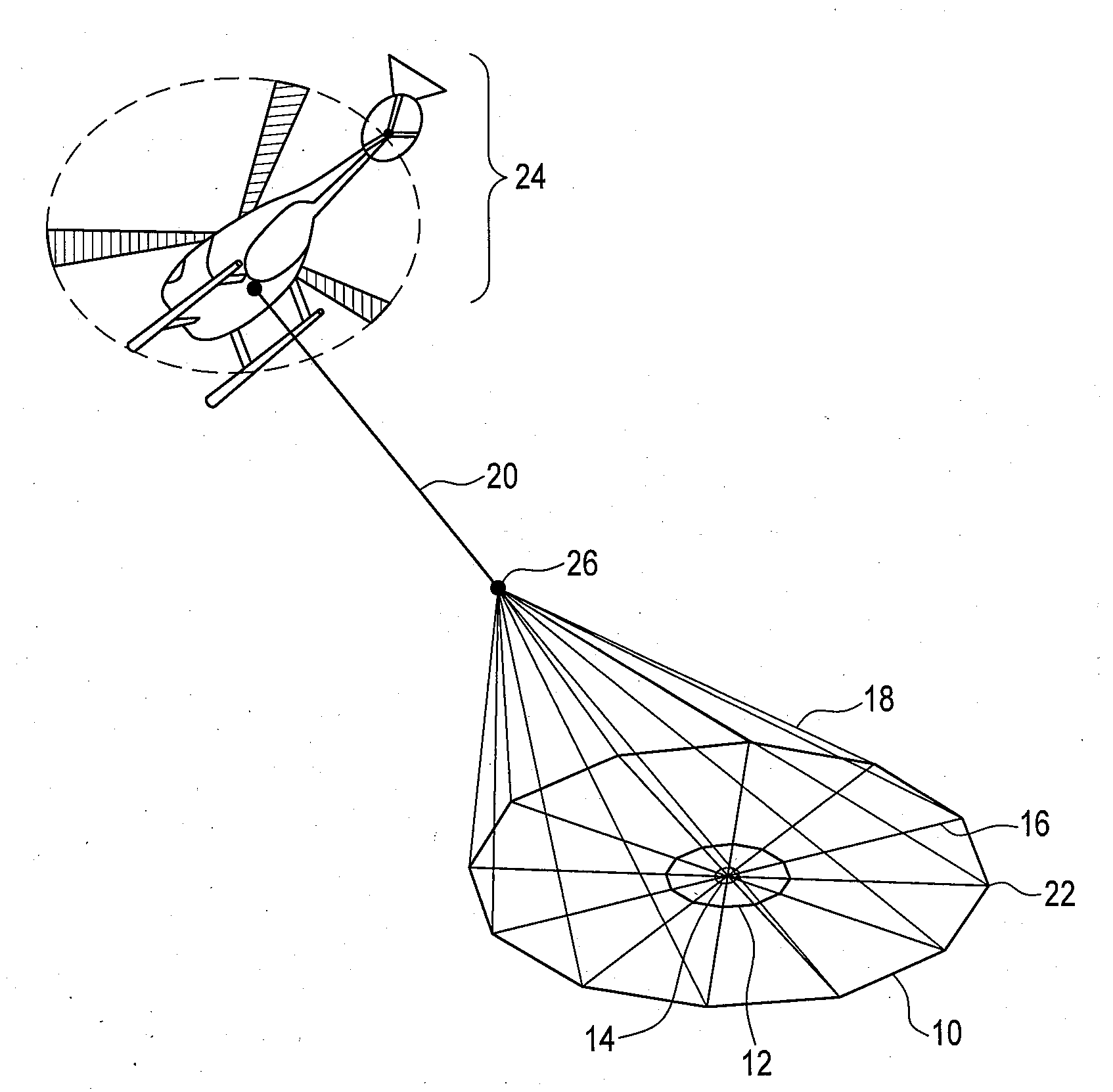
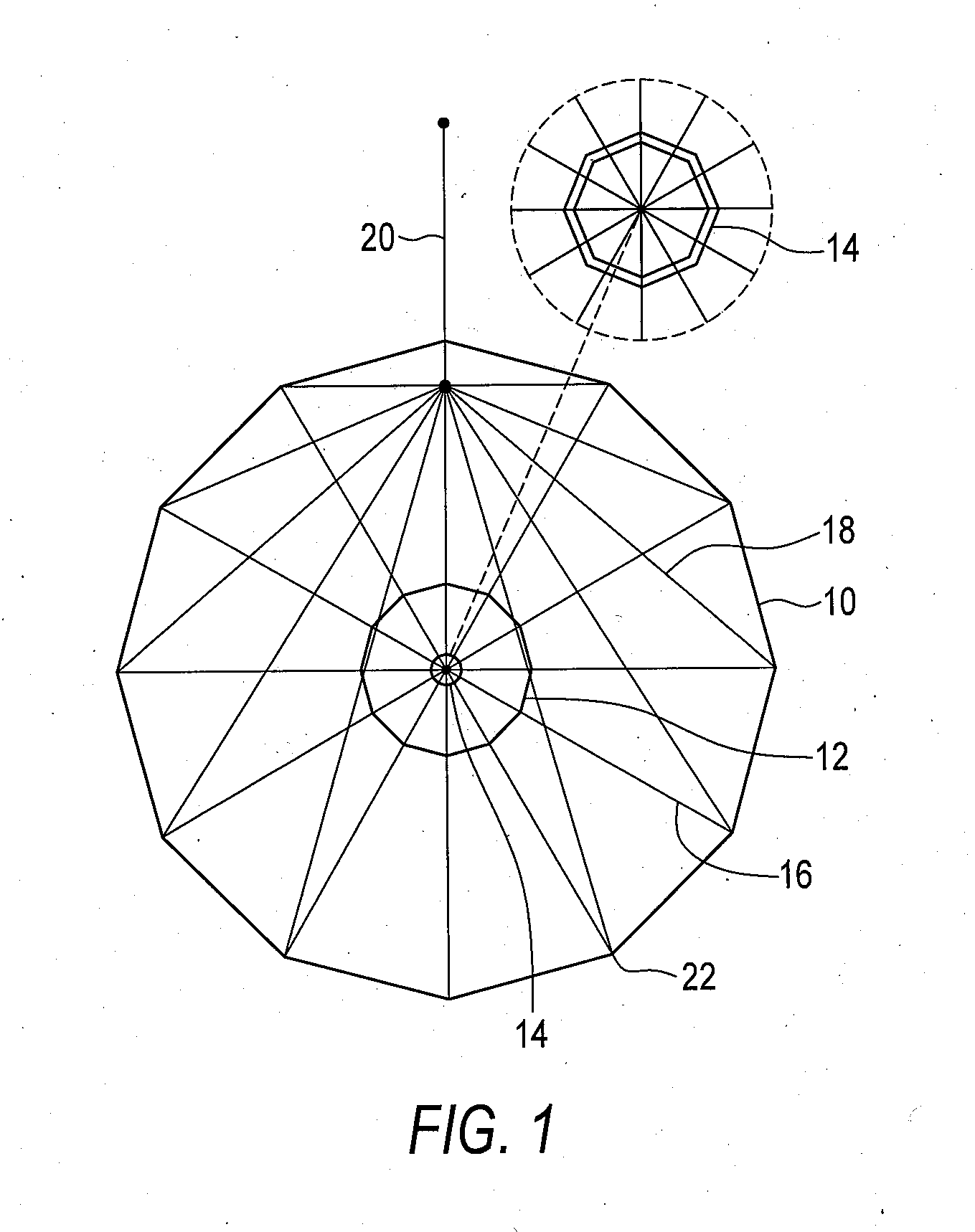
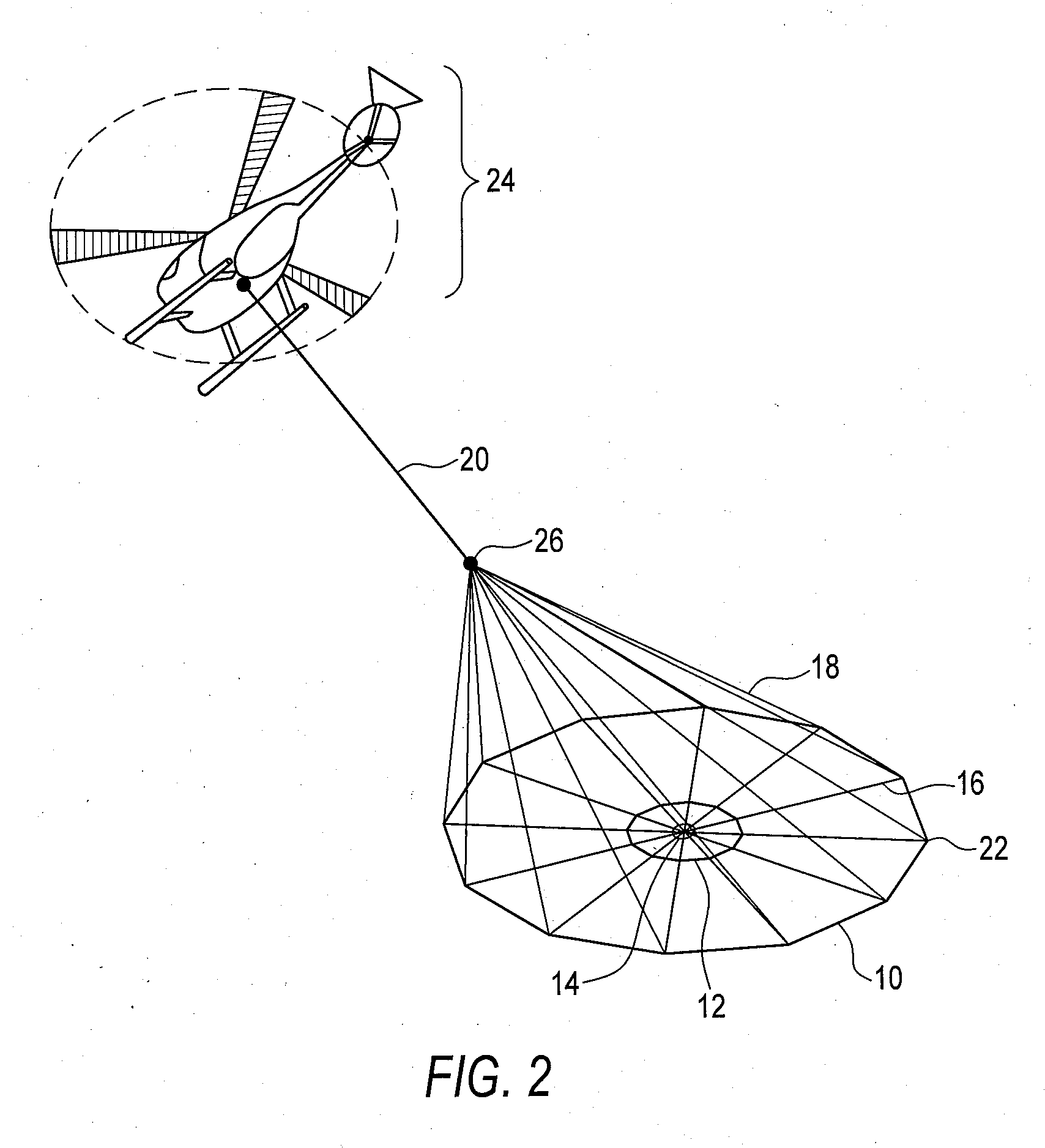
[0033]The present invention relates to a HTEM system that includes a semi-rigid bucking coil and means for determining the magnetic field B from the measured signal dB / dt. The bucking coil may be positioned in a concentric coplanar manner relative to a transmitter coil and receiver coil, in order to minimize spurious signals at the receiver coil during data acquisition time. Signals gathered by the system may be further processed by a signal processing means. Moreover, measurements performed upon data generated by the system may be performed upon the entire period of a current waveform applied to the transmitter and bucking coils.

[0034]The addition of a bucking coil can increase the suspension mechanical complexity and structure weight, but has the advantage of keeping the signal within the ADC dynamic range. The positioning and stability of the bucking coil is made possible by the present invention by placing the bucking coil at the centre of the main transmitter coil in order to m...


PUM


Abstract

The present invention relates to a HTEM system that includes a semi-rigid bucking coil and an algorithm to determine the magnetic field B from the measured signal dB/dt. The bucking coil may be positioned in a concentric coplanar manner relative to a transmitter coil and receiver coil, in order to minimize spurious signals at the receiver coil during data acquisition time. Signals gathered by the system may be further processed by a signal processing means. Moreover, measurements performed upon data generated by the system may be performed upon the entire period of a current waveform applied to the transmitter and bucking coils.

Description

FIELD OF INVENTION[0001]This invention relates in general to the field of geophysical electromagnetic measurements and more particularly to a method and system of obtaining a B-field using time domain electromagnetic measurements generated by way of an apparatus including a bucking coil and a signal processing means.BACKGROUND OF THE INVENTION[0002]Geophysical electromagnetic (EM) techniques may be effective in the determination of the electrical conductivity of soils, rocks and other conductive material at depths from the surface up to about three kilometers. Conductivity distribution at such depths is of great interest to those involved in mapping base metal and uranium deposits, aquifers and other geological formations.[0003]Geophysical EM methods involve measurement of time-varying magnetic fields near the earth's surface produced by a primary magnetic field and modeling of the ground conductivity distributions. These magnetic fields are generated either by a periodic current ap...

Claims


Application Information

Patent Timeline
Patent Type & Authority Applications(United States)
IPC IPC(8): G01V3/16G01V3/00
CPCG01V3/165
Inventor KUZMIN, PETR VALENTINOVICHMORRISON, EDWARD BEVERLY
Owner GEOTECH
Why Eureka
Try Eureka