Phosphor-Converted LED

a technology of phosphor and led light, which is applied in the direction of semiconductor devices, semiconductor/solid-state device details, electrical equipment, etc., can solve the problems of increasing packaging costs, light in a relatively narrow spectral band, and increasing the cost of packaging dies

Active Publication Date: 2010-03-04
BRIDGELUX INC
View PDF3 Cites 79 Cited by
  • Summary
  • Abstract
  • Description
  • Claims
  • Application Information

AI Technical Summary

Benefits of technology

[0007]The present invention includes a light source and method for fabricating the same. The light source includes a die, a light conversion component and a scattering ring. The die emits light of a first wavelength through a top surface of the die and one or more side surfaces of the die, the die being bonded to a surface of a mounting substrate. The light conversion component includes a layer of luminescent material that converts light of the first wavelength to light of a second wavelength, the light conversion component having a bottom surface bonded to the top surface of the die. The light conversion component has lateral dimensions such that a space exists around the die, the space being bounded by the substrate and the light conversion component. The scattering ring surrounds the side surfaces of the die and is positioned in the space such that a portion of the light emitted from the side surfaces of the die is scattered into the light conversion component by the scattering ring. In one aspect of the invention, the scattering ring includes a transparent material having particles suspended therein. In another aspect of the invention, the light conversion component includes a planar layer of transparent material having a luminescent material therein and a light processing layer that includes a layer of transparent material bonded to the planar layer, the light processing layer having a non-planar surface overlying the planar layer.
[0008]The light sources can be fabricated in groups of light sources in which a plurality of dies that emits light of a first wavelength through a top surface of the die and one or more side surfaces of the die are mounted to a surface of a mounting substrate. A sheet of light conversion components, each light conversion component including a layer of luminescent material that converts light of the first wavelength to light of a second wavelength, is positioned over the mounting substrate. Each light conversion component corresponding to one of the dies and being aligned with that die such that a bottom surface of that light conversion component is positioned over the top surface of that die. The sheet of light conversion components is then bonded to the top surfaces of the dies. Each light conversion component has lateral dimensions chosen such that a space exists around the corresponding die, the space is bounded by the substrate and the corresponding light conversion component. A scattering ring surrounding the side surfaces of each die is then generated. The scattering ring is positioned in the space around the die such that a portion of the light emitted from the side surfaces of that die is scattered into the light conversion component corresponding to that die by the scattering ring. In one aspect of the invention, the scattering rings include a transparent material having particles suspended therein. The transparent material has a liquid precursor that wets the bottom surface of the light conversion component and a surface of the substrate. The scattering rings are generated by suspending the scattering particles in the liquid precursor to form a liquid ring precursor, introducing the liquid ring precursor into the spaces around the dies, and curing the liquid ring precursor to form the transparent medium in which the scattering particles are suspended. In another aspect of the invention, the liquid precursor is drawn into the space by capillary action.

Problems solved by technology

Unfortunately, LEDs produce light in a relatively narrow spectral band.
The cost of packaging the dies represents a significant fraction of the cost of the final light source.
The packaging cost is increased by the need to capture light leaving the sides of the die.
The packaging costs associated with providing a constant thickness of phosphor and a reflector are substantial.
These processes are difficult to automate in a manner that guarantees uniformity of the light emitted across the die.
While designs in which the cups are created in a layer of material that is positioned over a number of dies have been suggested, the generation of the “cup layer” still represents a significant fraction of the cost of the final light source.

Method used


Image

  • Phosphor-Converted LED
  • Phosphor-Converted LED
  • Phosphor-Converted LED

Examples


Embodiment Construction

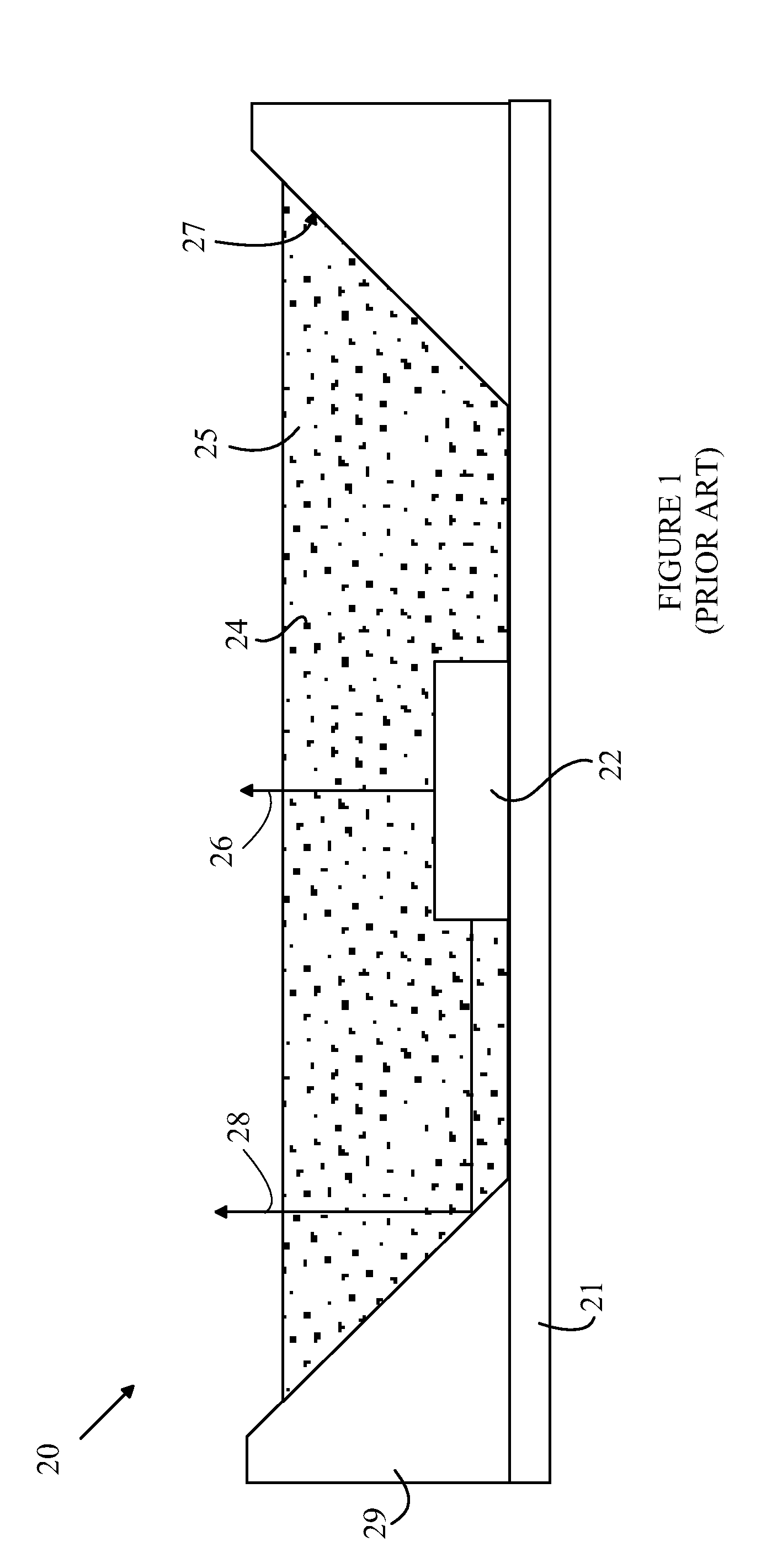
[0017]The manner in which the present invention provides its advantages can be more easily understood with reference to FIG. 1, which is a cross-sectional view of a typical prior art phosphor converted LED source 20. A light emitting semiconductor die 22 containing an LED is mounted within a cavity on a substrate 21. The LED is powered by contacts on the bottom side of die 22 that are connected to corresponding conductors on substrate 21. To simplify the drawing, the connections between die 22 and the conductors on substrate 21 have been omitted.

[0018]Light source 20 includes a cup 29 having reflecting sides 27. Cup 29 can be generated by boring a conical hole in a layer of material that is then bonded to substrate 21 after the walls of the hole are coated with a reflecting material. The cup is typically bonded to substrate 21 before die 22 is connected to substrate 21. However, embodiments in which the cup is created by boring a conical recess in substrate 21 are also known to the ...


PUM


Abstract

A light source and method for fabricating the same are disclosed. The light source includes a die, a light conversion component, and a scattering ring. The die emits light of a first wavelength through a top surface of the die and one or more side surfaces of the die, and is bonded to a mounting substrate. The light conversion component converts light of the first wavelength to light of a second wavelength, the light conversion component having a bottom surface bonded to the top surface of the die. The light conversion component has lateral dimensions such that a space exists around the die, the space being bounded by the substrate and the light conversion component. The scattering ring is positioned in the space such that a portion of the light emitted from the side surfaces of the die is scattered into the light conversion component.

Description

BACKGROUND OF THE INVENTION[0001]Light emitting diodes (LEDs) are attractive candidates for replacing conventional light sources such as incandescent lamps and fluorescent light sources. LEDs have substantially higher light conversion efficiencies than incandescent lamps and longer lifetimes than both types of conventional light sources. In addition, some types of LEDs now have higher conversion efficiencies than fluorescent light sources and still higher conversion efficiencies have been demonstrated in the laboratory. Finally, LEDs require lower voltages than fluorescent lamps, and hence, are better suited for applications in which the light source must be powered from a low-voltage source such as a battery or an internal computer DC power source.[0002]Unfortunately, LEDs produce light in a relatively narrow spectral band. To replace conventional lighting systems, LED-based sources that generate light that appears to be “white” to a human observer are required. A light source that...

Claims


Application Information

Patent Timeline
Patent Type & Authority Applications(United States)
IPC IPC(8): H01L33/00
CPCH01L25/0753H01L33/44H01L2933/0091H01L33/54H01L33/505H01L2224/16225H01L2224/32225H01L2224/73204H01L2924/0002H01L2924/00H01L33/50H01L33/52
Inventor WEST, SCOTT
Owner BRIDGELUX INC
Why Eureka
Try Eureka