
System and method for simultaneous communication on modbus and dnp 3.0 over ethernet for electronic power meter

a technology of electronic power meters and simultaneous communication, applied in multiplex communication, data switching networks, instruments, etc., can solve the problems of inefficient protocol management, inability to monitor the meter reading, and inability to accurately predict the meter reading, etc., to achieve the effect of easy incorporation

Active Publication Date: 2010-02-25
ELECTRO INDUSTRIES GAUGE TECH
View PDF99 Cites 31 Cited by
  • Summary
  • Abstract
  • Description
  • Claims
  • Application Information

AI Technical Summary

Benefits of technology

[0019]In a further embodiment of the present disclosure, a socket-type electric power meter provides concurrent operation of a web server, Modbus TCP and additional protocols which are supported by the power meter, thus allowing the power meter to be easily incorporated into existing power control systems as well as providing access to real-time web information, such as the revenue calculations, metering data and power quality data, using a standard web browser.

Problems solved by technology

Clearly, this approach relies very heavily on human intervention and, thus, is very costly, time-consuming, and prone to human error.
As the number of meters in a typical utility's service region has increased, in some cases into the millions, human meter reading has become prohibitive in terms of time and money.
For instance, while SCADA systems operate at peak performance using the DNP 3.0 protocol, this protocol is inefficient and difficult to manage when applied to metering departments, system planning, and estimation and power plant DCS systems.
This is often a costly endeavor, thus a need exists for a system for simultaneously communicating in a plurality of protocols between a monitoring instrument and the various departments in a central utility station.

Method used


Image

  • System and method for simultaneous communication on modbus and dnp 3.0 over ethernet for electronic power meter
  • System and method for simultaneous communication on modbus and dnp 3.0 over ethernet for electronic power meter
  • System and method for simultaneous communication on modbus and dnp 3.0 over ethernet for electronic power meter

Examples


Embodiment Construction

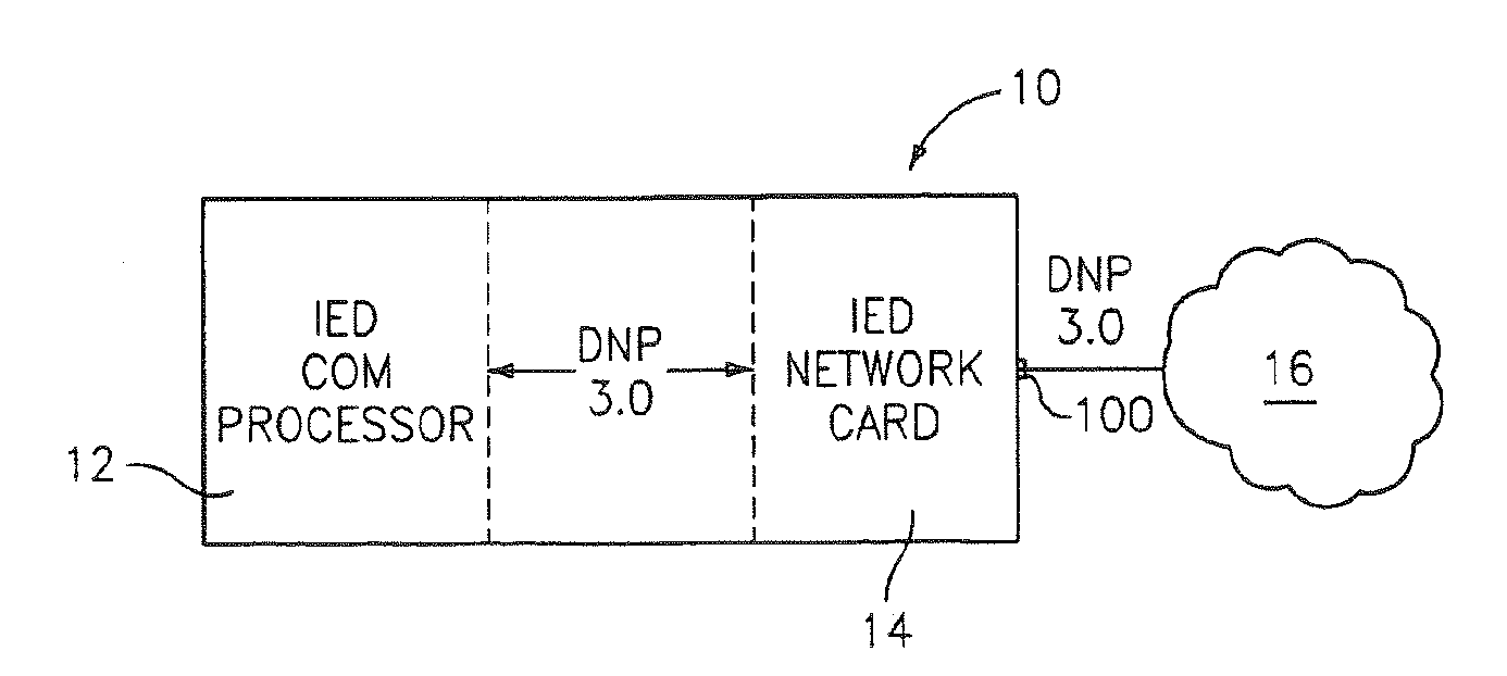
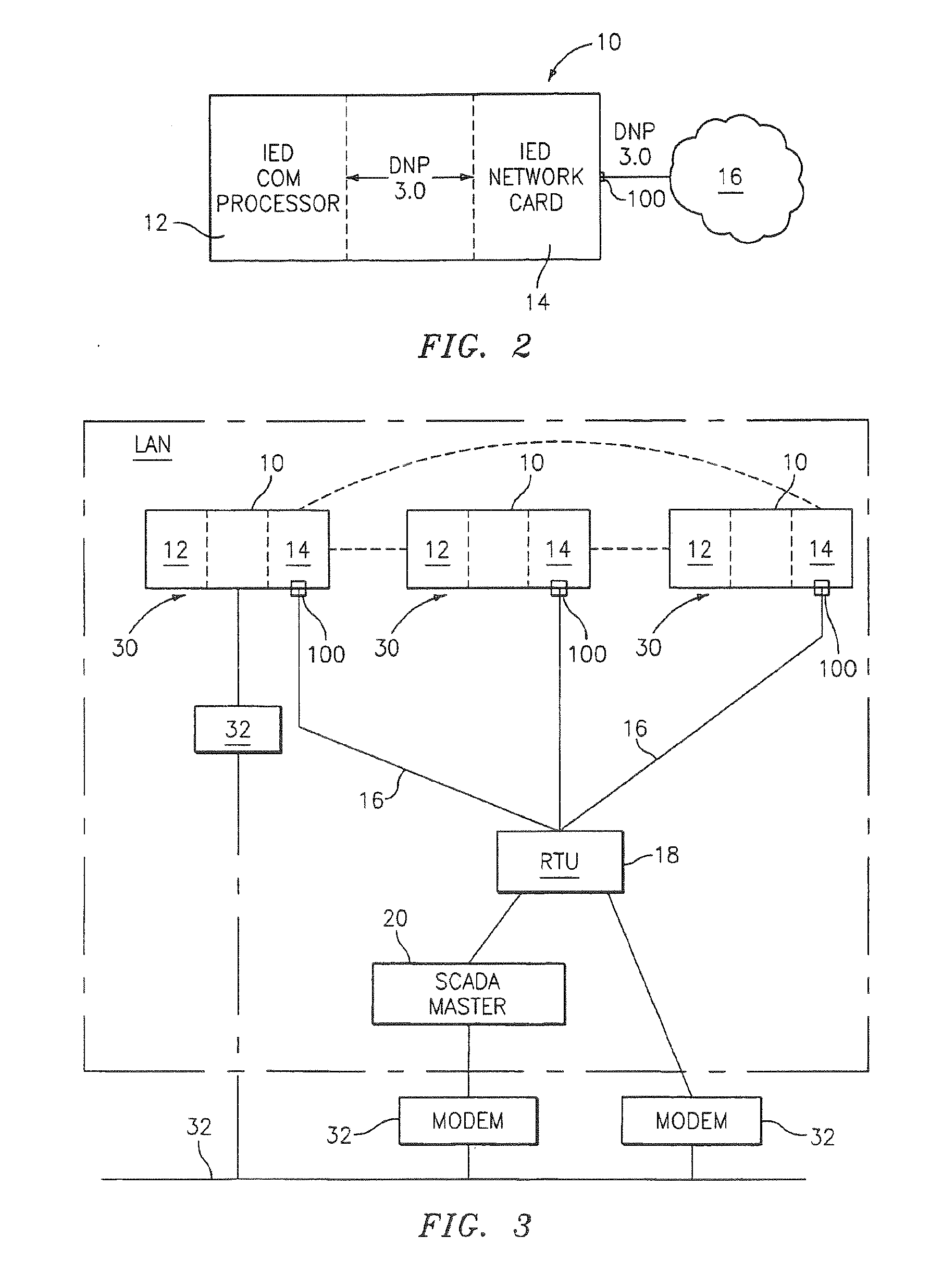
[0028]Referring to FIGS. 2 and 3, a metering device 10 is configured as an intelligent electronic metering device (IEMD). Functions of the IEMD 10 may include voltage transformation, regulation and control, power-factor (e.g., capacitor-bank) and load balancing, monitoring, protection of hardware, etc.

[0029]The IEMD 10 includes an IED COM processor 12 (FIG. 2) and a built-in IED Network Card 14 coupled to the processor 12 and operative to receive and transmit data between the IEMD 10 and a remote unit through an open socket 100 within an Ethernet TCP / IP medium 16 (FIGS. 2 and 3). Unlike a conventional IEMD communicating with a remote terminal unit (RTU) or SCADA master via a dedicated channel, the card 14 adapts a serial message from or to the processor 12 using the DNP 3.0 so as to receive and transmit the message via the Ethernet medium 16.

[0030]As illustrated in FIG. 2, the card 14 strips a message from the open socket 100 channel within the Ethernet and sends it through a serial...


PUM


Abstract

A system and method is provided for simultaneous communications on Modbus and DNP 3.0 over Ethernet for an electronic power meter. The system incorporates one or more protocol wrappers to provide compatibility with both Modbus and DNP based applications. The system removes the appropriate wrappers and routes the incoming data packet to its destination. Additionally, the system also wraps outgoing response packets with the appropriate protocol wrapper based on the related data packet wrappers.

Description

[0001]The present application is a continuation application of U.S. application Ser. No. 11 / 087,438 filed on Mar. 23, 2005, which a continuation-in-part application of U.S. application Ser. No. 10 / 969,592 filed on Oct. 20, 2004 by Kagan et al. entitled “SYSTEM AND METHOD FOR PROVIDING COMMUNICATION BETWEEN INTELLIGENT ELECTRONIC DEVICES VIA AN OPEN CHANNEL”, the entire contents of which are hereby incorporated by reference. In addition, the present application claims priority to a U.S. provisional patent application filed on Oct. 12, 2004 and assigned Application Ser. No. 60 / 617,689, the contents of which are incorporated herein by reference.BACKGROUND[0002]1. Field of the Disclosure[0003]The present disclosure relates generally to monitoring and control of metering systems. More particularly, the present disclosure relates to systems and methods for simultaneous communications on Modbus and DNP 3.0 over Ethernet for an electronic power meter.[0004]2. Description of the Related Art[...

Claims


Application Information

Patent Timeline
Patent Type & Authority Applications(United States)
IPC IPC(8): H04J3/22
CPCH04L12/4633H04L69/08G01R22/063Y04S20/30H04L12/40136
Inventor KAGAN, ERRANSLOTA, FREDRICKWANG, WEISPANIER, JOSEPH
Owner ELECTRO INDUSTRIES GAUGE TECH
Learn More