
Analyte test system using non-enzymatic analyte recognition elements

a technology of analyte recognition and test system, which is applied in the direction of biochemistry equipment, biochemistry apparatus and processes, nanotechnology, etc., can solve the problems of reducing the likelihood of a patient making a full recovery per unit, unnecessary treatment delay, and hazardous treatment, and achieves simple and disposable test elements favourable for point of care and home testing, and easy production of elements. , the effect of simple and convenient method

Inactive Publication Date: 2010-02-11
EGOMEDICAL TECH
View PDF30 Cites 42 Cited by
  • Summary
  • Abstract
  • Description
  • Claims
  • Application Information

AI Technical Summary

Benefits of technology

[0033]In a further aspect, the invention provides an analyte test system consisting of a meter device and an analyte test element, e.g. in shape of a strip, for non-enzymatic affinity reactions between an analyte of interest and a non-enzymatic analyte specific recognition element. For the integrated calibration and quality control mechanisms said analyte test system employs the standard addition methods utilising the sample distribution system of the analyte test element containing the required standards and / or quality controls. The system is optimised to perform immunoassays, receptor-assays, or other affinity assays in a swift and easy manner with a simple and disposable test element favourable for point of care and home testing.
[0034]The production of the inventive analyte test element involves only a small number of uncomplicated production steps enabling an inexpensive production of the element.

Problems solved by technology

Such treatments can be hazardous due to bacterial risk, expensive, and the likelihood of a patient making a full recovery is reduced per unit time after a disease has manifested itself within a patient's body.
A current problem therefore for physicians is their ability to provide a rapid and accurate test result to determine if a patient is suffering from a disease.
Indeed, such a protocol can be problematic for a patient since the time delay between the initial consultation and receiving of a test result can cause mutual stress and unnecessary delay of the treatment and therefore increased risk for patients.
However, point of care and ‘walk-in’ clinics are becoming prevalent in some countries to counteract the perceived inefficiency of Health Departments but the costs involved make them only attractive to the most affluent members of society.
In addition, test equipment at a physician's office may be expensive for some practices and some might prefer to rely on sending fluid samples to a laboratory for analysis.
Additionally, the cost of seeking medical treatment in some countries by visiting a physician may be prohibitively expensive for some individuals since not all health schemes are free at the PoC.
Various tests elements do exist for either home testing of physiological conditions such as for diabetes, pregnancy, and fertility but there exists minimal test equipment that can provide a simple diagnostic tool to provide information of a disease state and progress with a fast and accurate result at a point of care or at home.
However, up to now no analyte test system exists suitable for point of care or home settings, which can evaluate the non-enzymatic reaction between an analyte of interest and an analyte specific recognition element while performing an integrated calibration and / or quality control measurement for the analyte in question in a given physiological or aqueous sample fluid.

Method used


Image

  • Analyte test system using non-enzymatic analyte recognition elements
  • Analyte test system using non-enzymatic analyte recognition elements
  • Analyte test system using non-enzymatic analyte recognition elements

Examples


Embodiment Construction

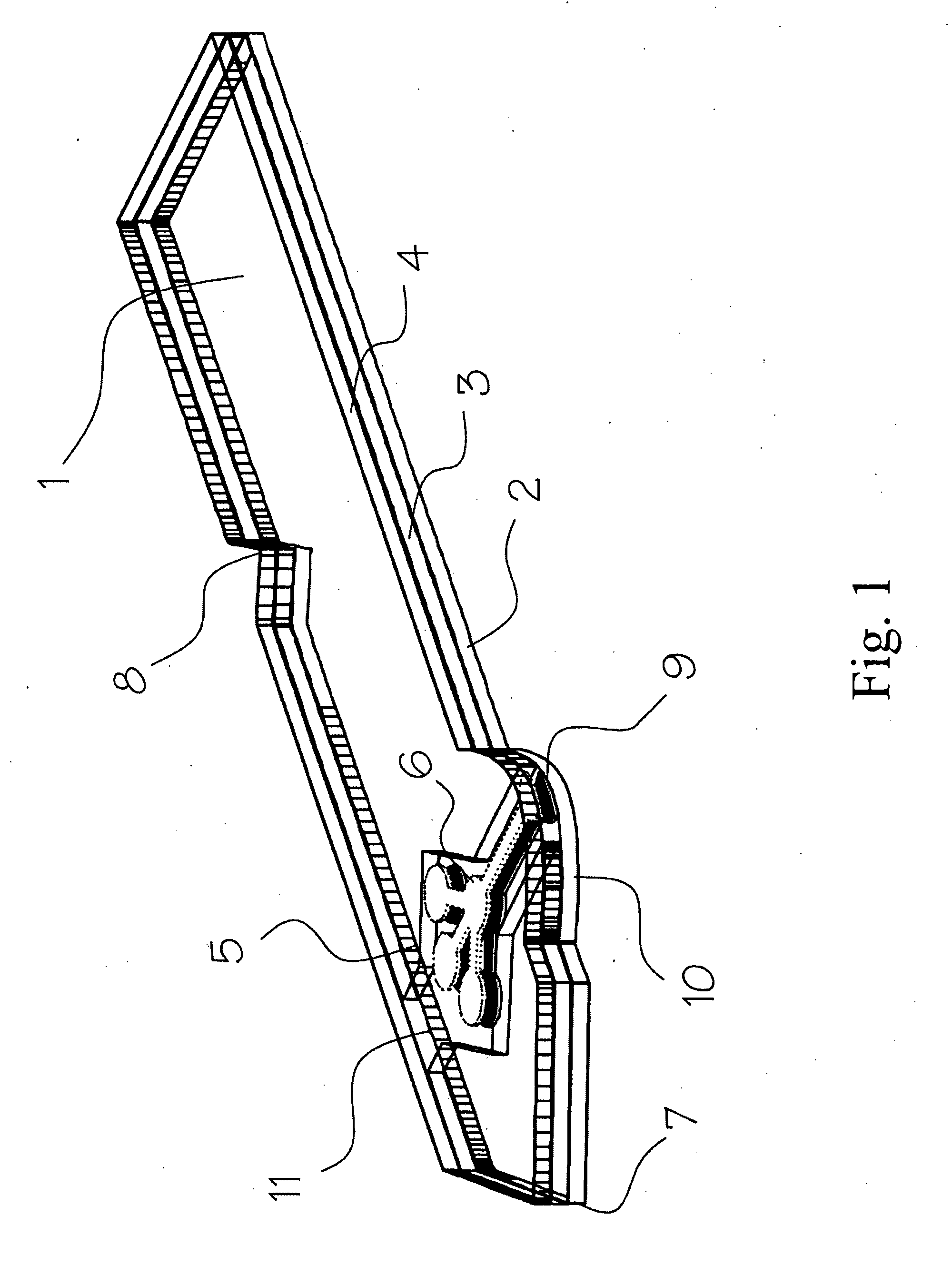
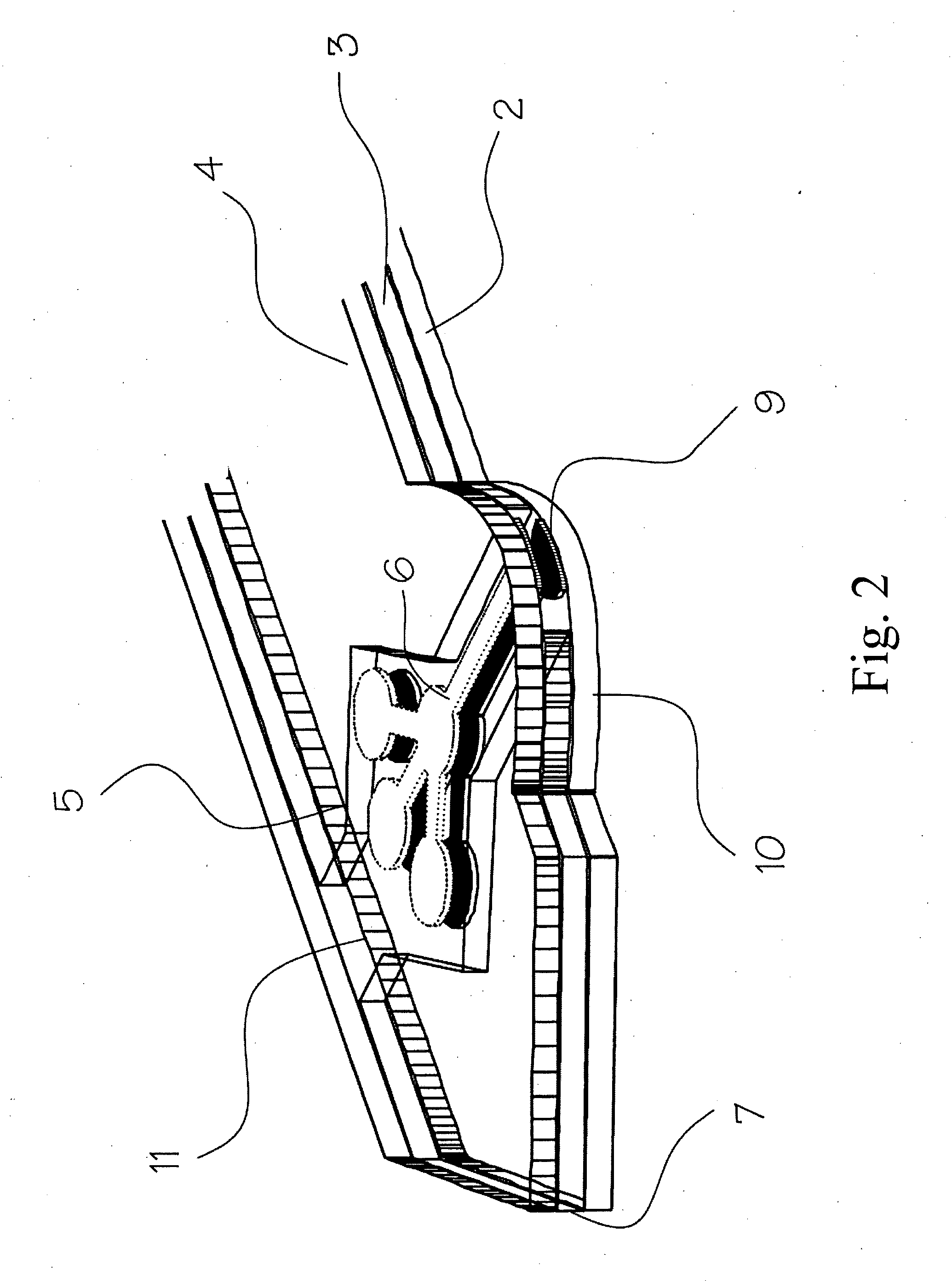
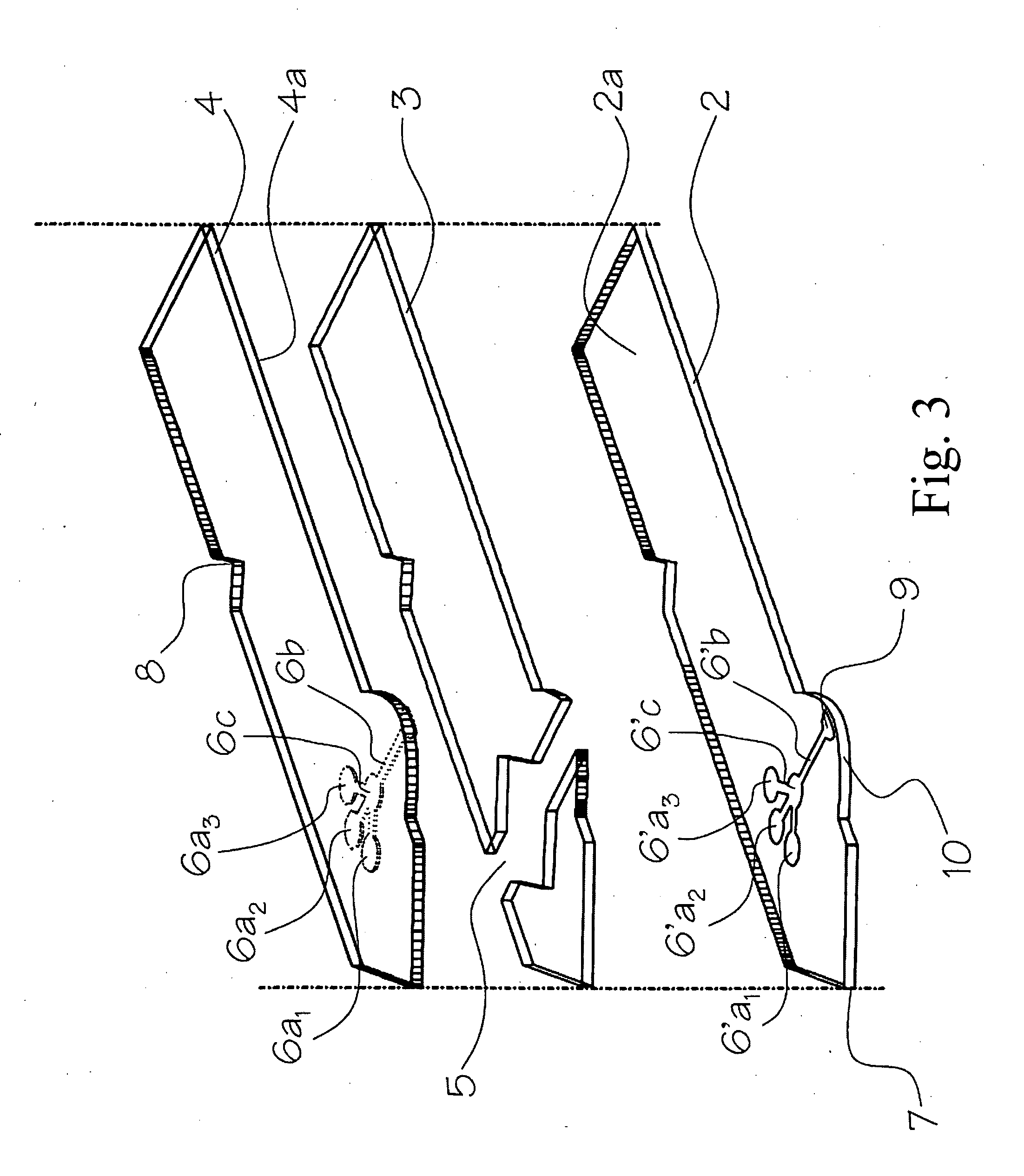
[0057]As shown in FIG. 1 and FIG. 2, the analyte test element 1 of the present invention is a multiple layer arrangement comprising a base layer 2, a centre layer 3 overlaying the base layer 2, and a cover layer 4 overlaying the centre layer 3. The centre layer 3 presents a discontinuity 5, which creates a hollow cavity in conjunction with the base layer 2 and the cover layer 4. Within said cavity there is located a sample distribution system 6 which is connected to a sample application area 9 located on one side of the analyte test strip. The sample application area 9 as interface to the user is preferably formed by a convex curve 10 extending from one major side of the analyte test strip for easier application of the sample. Opposite to the sample application area 9, 10 on the second major side of the analyte test strip is the location of an air vent 11 allowing the displacement of air while the physiological or aqueous fluid is distributed to the predetermined detection areas 6a,...


PUM

PropertyMeasurementUnit
Fractionaaaaaaaaaa
Concentrationaaaaaaaaaa
Hydrophilicityaaaaaaaaaa

Abstract

An analyte test element for the qualitative and / or quantitative determination of at least one analyte in a physiological or aqueous sample fluid having a first surface (2a) and a second surface (4a) in a predetermined distance opposite from each other, said both surfaces are provided with two substantially equivalent patterns forming areas of high and low surface energy which are aligned mostly congruent, whereby the areas of high surface energy (6, 6′) create a sample distribution system with at least two detection areas (6a, 6′a), said at least one of the detection areas (6a, 6′a) of the first and second surfaces (2a, 4a) is provided with at least one non-enzymatic recognition element (32). The analyte test element is suitable for analyte test systems evaluating the affinity reaction between an analyte of interest and a recognition element and therefore provides a suitable test system to perform immunoassays, receptor-assays, or other affinity assays with a simple test element containing qualitative or quantitative calibration mechanisms suitable for point of care and home settings.

Description

FIELD OF THE INVENTION[0001]The invention relates to an analyte test system for determining qualitatively and quantitatively an analyte in a liquid medium, such as an aqueous or physiological sample fluid. In a preferred embodiment the present invention relates to an analyte test system to qualify and quantify the reaction between a host and a guest molecule, particularly to affinity assays and immunoassays.BACKGROUND OF THE INVENTION[0002]The diagnosis and confirmation of various illnesses and health status has been a major task for health care professionals since medicine has been practised. Currently, health physicians have at their disposal a multitude of diagnostic techniques available to them which allow the accurate diagnosis and confirmation of various diseases and patient conditions in bodily fluids. The determination of different patient conditions in particular diseases are of paramount importance to health practitioners, whereas different needs and requirements have to b...

Claims


Application Information

Patent Timeline
IPC IPC(8): C12Q1/68C12M1/34G01N33/53
CPCB01L3/502707G01N33/54393B01L3/502792B01L2200/0684B01L2300/0816B01L2300/0825B01L2300/0864B01L2300/0887B01L2300/089B01L2400/0406B82Y5/00C12Q1/6834G01N21/8483G01N33/526G01N33/54386B01L3/502761
Inventor STIENE, MATTHIASHORSTKOTTE, ELKEKUHLMEIER, DIRKJONES, EURIG WYN
Owner EGOMEDICAL TECH
Learn More