
Enhanced HVAC system and method

a technology of hvac system and hvac air, which is applied in the field of heating ventilation and air conditioning (hvac), can solve the problems of affecting the efficiency of small scale operations, and requiring maintenan

Active Publication Date: 2010-02-11
TANGREDI PATRICIA
View PDF41 Cites 47 Cited by
  • Summary
  • Abstract
  • Description
  • Claims
  • Application Information

AI Technical Summary

Problems solved by technology

Unfortunately, the evaporative cooling towers can be costly to maintain involving cleaning of evaporative surfaces and remedying build up of toxic salts and metals in water supplies.
Other challenges are involved when attempts are made to scale down evaporative cooling towers for smaller sized applications.
Often smaller scaled operations are forced to forego use of evaporative cooling towers because of size scaling issues.
Consequently, efficiency of these smaller applications can suffer.
Unfortunately, liquid already condensed on a portion of the surface can interfere with further condensation thereby hindering efficiencies.

Method used

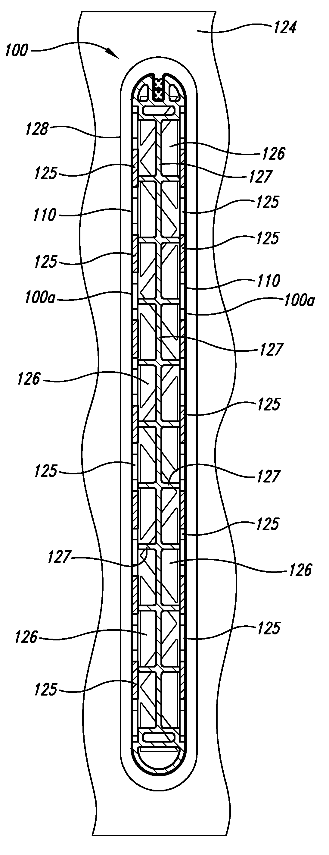
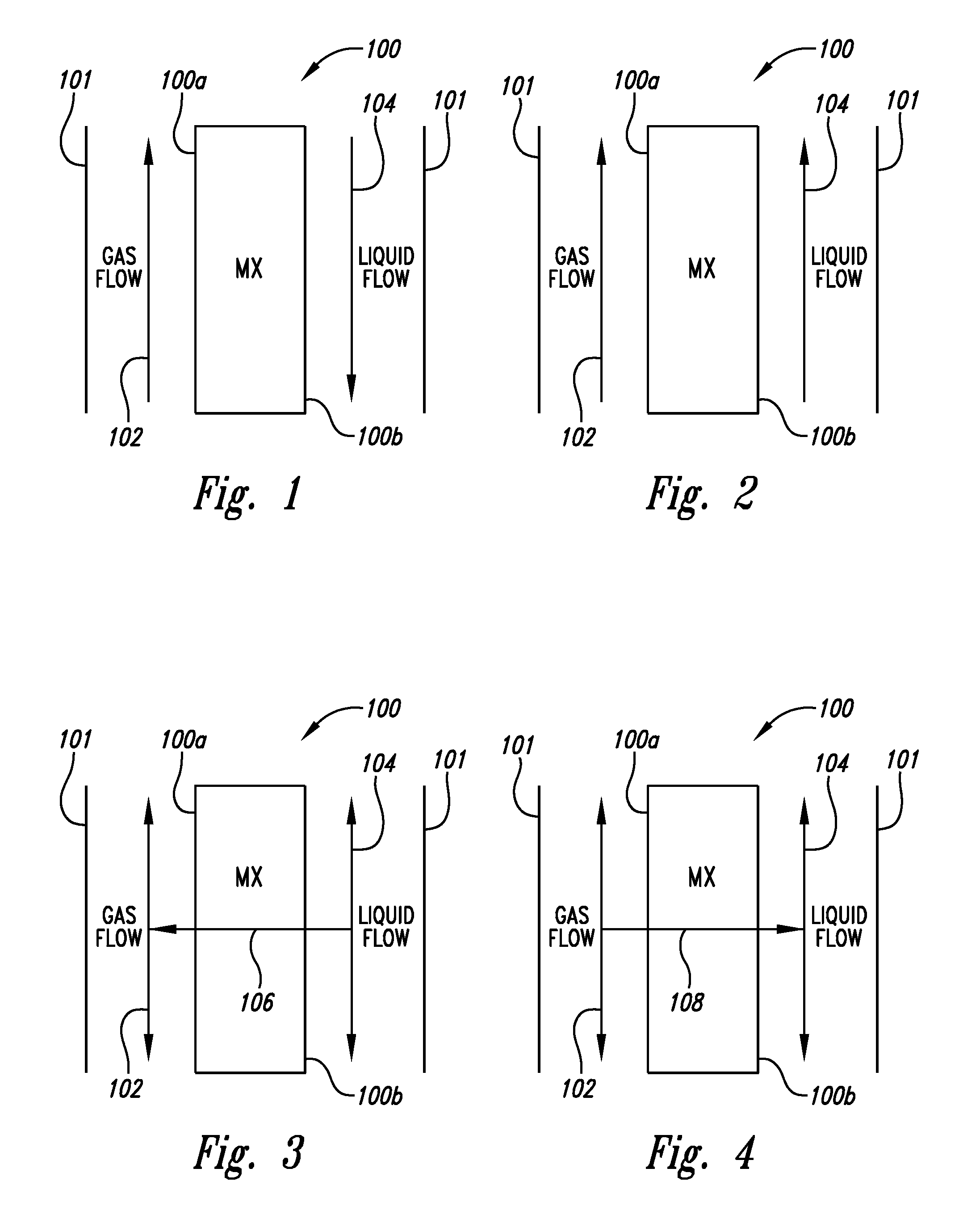
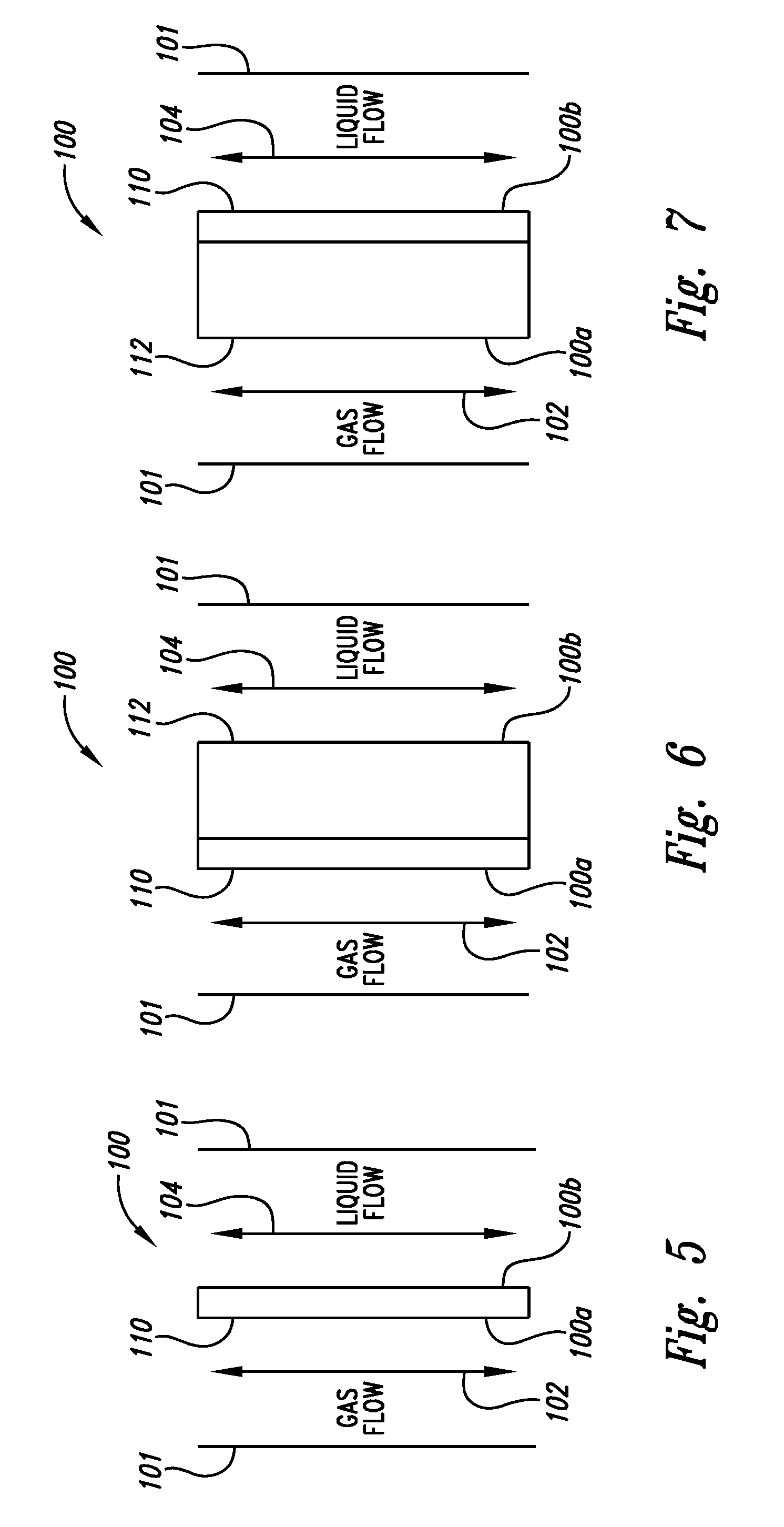

Image

  • Enhanced HVAC system and method
  • Enhanced HVAC system and method
  • Enhanced HVAC system and method

Examples


example 1

[0067]

Enthalpy AbsorberOutletInlet AirAirg-H20 / g-H20 / InletOutletAir FlowInlet AirOutlet Airkg drykg dryH2OH2OH2O FlowcfmDeg C.Deg C.airairDeg C.Deg C.gpm66.82618.49.98.96.615.1.3786.527.718.511.439.326.610.2.37100.025.318.69.899.386.610.2.37

[0068]As can be seen in the chart the enthalpy absorber cooled and dehumidified the air while warming the water stream. This was done without generating liquid water at the membrane air interface. At 86 cfm the enthalpy absorber removed 18% of the water in the airstream.

example 2

[0069]

Enthalpy DesorberOutletInlet AirAirg-H20 / g-H20 / InletOutletAir FlowInlet AirOutlet Airkg drykg dryH2OH2OH2O FlowcfmDeg C.Deg C.airairDeg C.Deg C.gpm66.83529.39.618.732.928.3.3786.53529.19.217.732.928.0.37100.03529.19.217.132.927.9.37

[0070]As can be seen in chart, the enthalpy desorber cooled the water stream while cooling and humidifying the air. This was done without liquid water being present at the membrane air interface. At 67 cfm the enthalpy desorber increased the amount of water in the air stream by 95%.

example 3

[0071]A second enthalpy exchanger was built with 32 membrane layers each with about 508 cm (200 square inches) of transfer area. The plastic PVC flow fields were of a different design but the operational principles of the second exchanger were identical to the first 5-membrane layer exchanger. A test was run on this larger exchanger as an enthalpy desorber. Here 32 degrees Celsius (90 degrees Fahrenheit) water was pumped through the exchanger. The water flow was subdivided by the PVC flow fields such that there was an even flow to each membrane; each membrane receiving up to 11 gallons per minute of water flow. The water flow rate was a variable in the test and is shown as the abscissa on the chart below.

[0072]As shown in FIG. 14, plotted against the water flow rate were several airflows of a known velocity, dry bulb temperature of 35 degrees Celsius (95 degrees Fahrenheit) and humidity expressed a wet bulb temperature of 14 degrees Celsius (58 degrees Fahrenheit) The thermal energy...


PUM

PropertyMeasurementUnit
Porosityaaaaaaaaaa
Weightaaaaaaaaaa
Weightaaaaaaaaaa

Abstract

Particular embodiments disclosed herein relate to methods, compositions, and systems relating generally to heating, ventilation, and air conditioning (HVAC) systems, and more specifically, to HVAC systems that transfer sensible and / or latent energy between air streams, humidify and / or dehumidify air streams. In certain embodiments, a polymeric membrane is utilized for fluid exchange, with or without an additional support. Certain embodiments allow for individual regulation of air temperature and humidity.

Description

CROSS REFERENCE TO RELATED APPLICATIONS[0001]This application claims priority from U.S. Provisional Application Ser. No. 60 / 846,747, filed Sep. 25, 2006.BACKGROUND OF THE INVENTION[0002]1. Field of the Invention[0003]The present invention relates generally to the field of heating, ventilation, and air conditioning (HVAC).[0004]2. Description of the Related Art[0005]Existing HVAC systems use heat of condensation and / or heat of vaporization of a liquid, such as water, to adjust temperature and humidity within a structure such as a dwelling, building, vehicle or other region such as for a localized environment or functioning apparatus. Conventional HVAC systems can have evaporative cooling towers, which dissipate heat carried by a liquid, such as water, by evaporating a portion of the liquid.[0006]Unfortunately, the evaporative cooling towers can be costly to maintain involving cleaning of evaporative surfaces and remedying build up of toxic salts and metals in water supplies. Other ch...

Claims


Application Information

Patent Timeline
IPC IPC(8): B01D53/22F28F1/00
CPCF24F5/0035F24F2003/1435Y02B30/545F28D21/0015F28F21/062F28D1/05383Y02B30/54
Inventor EHRENBERG, SCOTT G.HUYNH, HUNGJOHNSON, BRIAN
Owner TANGREDI PATRICIA
Learn More