Eureka AIR delivers breakthrough ideas for toughest innovation challenges, trusted by R&D personnel around the world.

Subcutaneous implantable lead

Active Publication Date: 2010-02-04
MEDTRONIC INC
View PDF14 Cites 1 Cited by
  • Summary
  • Abstract
  • Description
  • Claims
  • Application Information

AI Technical Summary

Problems solved by technology

Withdrawing the sheath from the channel can undesirably snag the lead and move it from is desired subcutaneous position.

Method used


Image

  • Subcutaneous implantable lead
  • Subcutaneous implantable lead
  • Subcutaneous implantable lead

Examples


Embodiment Construction

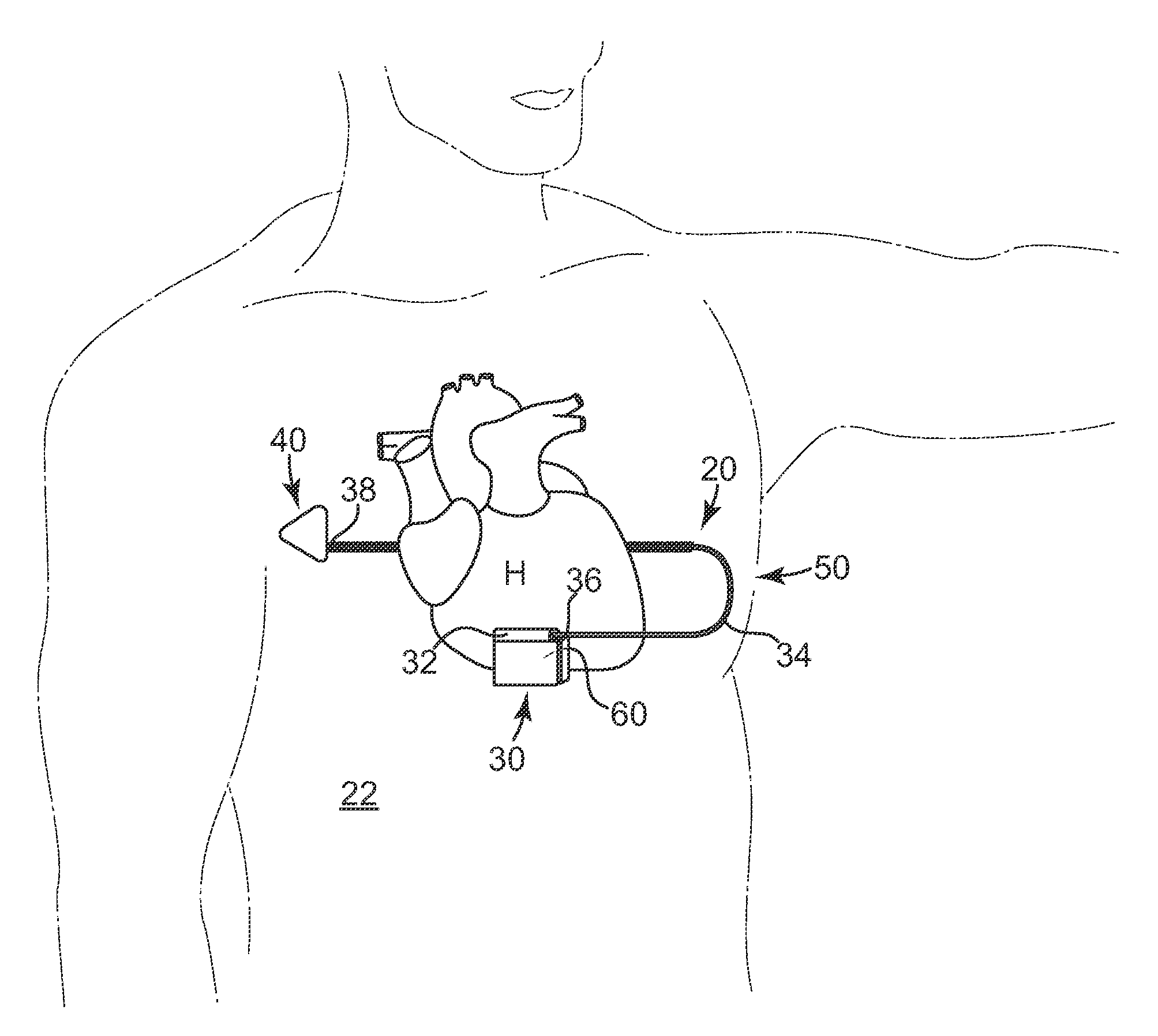
[0018]According to an embodiment of the present invention, a subcutaneous implantable device is provided having an arrow-shaped lead tip configured to enable subcutaneous placement of the lead without introducing the lead down a sheath. The lead tip is configured to enable direct placement of the lead with a tunneling tool and minimizes the possibility of undesirably puncturing the thoracic muscle or skin.

[0019]In one embodiment, the arrow-shaped lead tip includes a trailing end that is coupled to the lead, and first and second non-parallel sides extending from the trailing end that converge to a leading end that is configured to wedge between tissue layers as the lead is advanced subcutaneously.

[0020]In one embodiment, the lead tip provides increased electrically conductive surface for the lead, which contributes to improved defibrillation shock delivery.

[0021]It is to be understood that features of the various exemplary embodiments described herein may be combined with each other,...


PUM


Abstract

A subcutaneous implantable device is provided that includes a defibrillation electrode disposed along a portion of a lead, and a lead tip connected to the lead. The lead tip includes a trailing end coupled to a distal end of the lead, and first and second non-parallel sides extending from the trailing end that converge to a leading end that is configured to wedge between tissue layers as the lead is advanced subcutaneously.

Description

FIELD OF THE INVENTION[0001]The present invention relates generally to subcutaneous implantable leads, and more particularly, to a subcutaneous implantable lead having a lead tip configured to assist in subcutaneously tunneling the lead without the use of a sheath.BACKGROUND OF THE INVENTION[0002]Many types of implantable medical devices have been clinically implanted into patient's bodies over the last twenty years that deliver relatively high-energy cardioversion and / or defibrillation shocks to a patient's heart when a malignant tachyarrhythmia, e.g., atrial or ventricular fibrillation, is detected. Cardioversion shocks are delivered in synchrony with a detected R-wave when fibrillation detection criteria are met, whereas defibrillation shocks are delivered when fibrillation criteria are met and an R-wave cannot be discerned from the electrocardiogram. The earliest clinically released automatic implantable defibrillators (AIDs) that were implanted in human patients provided a high...

Claims


Application Information

Patent Timeline
IPC IPC(8): A61N1/39A61N1/05
CPCA61N1/3962A61N1/0504A61N1/39622
Inventor HAVEL, WILLIAM J.LAZEROMS, MARKUS J.C.RUTTEN, JEAN J.G.SMITS, KAREL F.A.A.
Owner MEDTRONIC INC
Why Eureka
Eureka Blog
Learn More