
Sensor-Based Occupancy and Behavior Prediction Method for Intelligently Controlling Energy Consumption Within a Building

a technology of occupancy and behavior prediction, applied in the direction of program control, heating types, instruments, etc., can solve the problems of sacrificing comfort level, re-programming is considered too difficult of a task, and the time period during which a building will be occupied is not always well known, so as to achieve the effect of reducing energy costs and sacrificing comfort level

Inactive Publication Date: 2010-02-04
ROBERT BOSCH GMBH
View PDF14 Cites 390 Cited by
  • Summary
  • Abstract
  • Description
  • Claims
  • Application Information

AI Technical Summary

Benefits of technology

[0017]An advantage of the present invention is that energy costs may be reduced without sacrificing comfort level.
is that energy costs may be reduced without sacrificing comfort level.

Problems solved by technology

A problem with such known HVAC control systems is that the time periods during which a building will be occupied are not always well known.
Even when changes in occupancy schedules are known, the HVAC control system is often not re-programmed according to the new schedule because either no one who knows how to re-program the system is available, re-programming is considered to be too difficult of a task, or re-programming of the HVAC control system is completely forgotten about.
Thus, when changes in occupancy schedules take place, the HVAC system is often operated when it need not be, and / or occupants suffer through uncomfortable temperatures when the HVAC system is shut down.
Another problem is that, because HVAC control system programmers are aware of the uncertainty of future occupancy schedules, the programmers intentionally err on the side of operating the HVAC for too great a portion of the day.
Although this practice may result in more comfort for the occupants, it certainly results in instances of the HVAC system operating when there is no need for it to do so.

Method used


Image

  • Sensor-Based Occupancy and Behavior Prediction Method for Intelligently Controlling Energy Consumption Within a Building
  • Sensor-Based Occupancy and Behavior Prediction Method for Intelligently Controlling Energy Consumption Within a Building
  • Sensor-Based Occupancy and Behavior Prediction Method for Intelligently Controlling Energy Consumption Within a Building

Examples


Embodiment Construction

[0026]Some portions of the following description are presented in terms of algorithms and operations data. Unless otherwise stated herein, or apparent from the description, terms such as “calculating”, “collecting”, “controlling”, “determining”, “predicting”, “processing” or “computing”, or similar terms, refer the actions of a computing device that may perform these actions automatically, i.e., without human intervention, after being programmed to do so.

[0027]The embodiments hereinafter disclosed are not intended to be exhaustive or limit the invention to the precise forms disclosed in the following description. Rather the embodiments are chosen and described so that others skilled in the art may utilize its teachings.

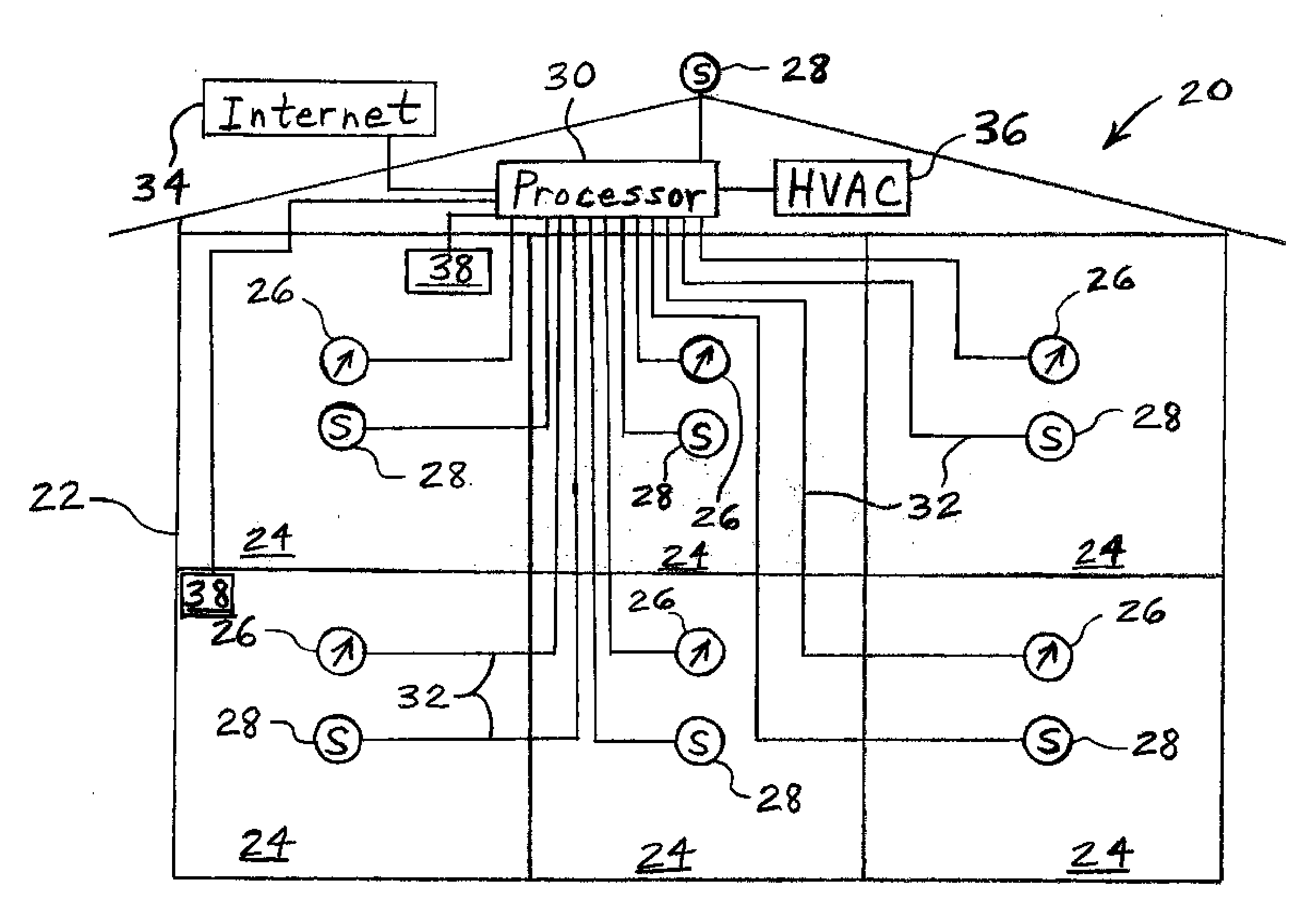
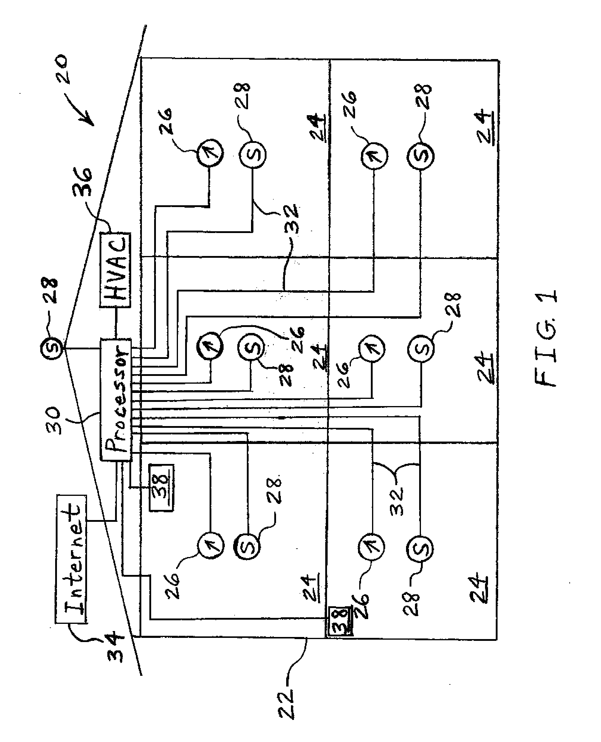
[0028]Referring now to FIG. 1, there is shown one embodiment of a sensor-based HVAC control system 20 of the present invention including a building 22 having a plurality of rooms 24. Within each room 24, there may be one or more energy consumption sensing device 26 an...


PUM


Abstract

A method for controlling energy consumption within a building includes providing at least one environment sensing device and at least one energy consumption sensing device associated with the building. Current data is collected from the environment sensing device and the energy consumption sensing device along with associated time-of-day data. A value of a future energy consumption parameter is predicted based upon the collected current data, the associated time-of-day data, and historic data collected from the environment sensing device and the energy consumption sensing device. A profile of future costs per unit of energy consumption as a function of time is determined. Energy consumption is controlled dependent upon the predicted future energy consumption parameter value and the determined profile of energy consumption costs.

Description

COPYRIGHT NOTICE[0001]Portions of this document are subject to copyright protection. The copyright owner does not object to facsimile reproduction of the patent document as it is made available by the U.S. Patent and Trademark Office. However, the copyright owner reserves all copyrights in the software described herein and shown in the drawings. The following notice applies to the software described and illustrated herein: Copyright© 2008, Robert Bosch GmbH, All Rights Reserved.BACKGROUND[0002]1. Field of the Invention[0003]The present invention relates to a method for controlling energy consumption within a building, and, more particularly, to a method for controlling energy consumption within a building in response to sensor outputs.[0004]2. Description of the Related Art[0005]Energy prices are widely varying on a daily basis and are steadily increasing. Minimization of heating and air conditioning costs for a building, while maintaining comfort, must be based on identification of...

Claims


Application Information

Patent Timeline
IPC IPC(8): G05D23/30
CPCF24F11/001Y04S20/244F24F2011/0075G05B2219/2614G05B2219/2639H02J3/14H02J2003/003H02J2003/143H02J2003/146Y02B70/3225Y02B70/3266Y02B70/3275Y04S20/222Y04S20/224Y04S20/242F24F11/0034G05B15/02G05B19/418G05B2219/2642F24F11/32F24F11/30F24F2110/00F24F2120/10F24F11/46H02J3/003H02J2310/14H02J2310/64Y02B70/30Y04S50/10
Inventor HOEYNCK, MICHAELANDREWS, BURTON W.
Owner ROBERT BOSCH GMBH
Learn More