
System and method for emulating vehicle ignition-switched power

Inactive Publication Date: 2010-01-28
HAMILTON PERFORMANCE ELECTRONICS
View PDF15 Cites 82 Cited by
  • Summary
  • Abstract
  • Description
  • Claims
  • Application Information

AI Technical Summary

Benefits of technology

[0008]The invention provides a system and method that emulates the functionality of ignition-switched power in a vehicle. One advantage of the present invention is that it protects the vehicle battery from undesirable accessory battery drain. In addition, the invention, in certain embodiments, includes standardized connectors which allow it to be easily installed to the vehicle as well as to the accessory. Finally, embodiments of the invention may be used in nearly any 1996 model year (or later) OBD-II compliant vehicle.
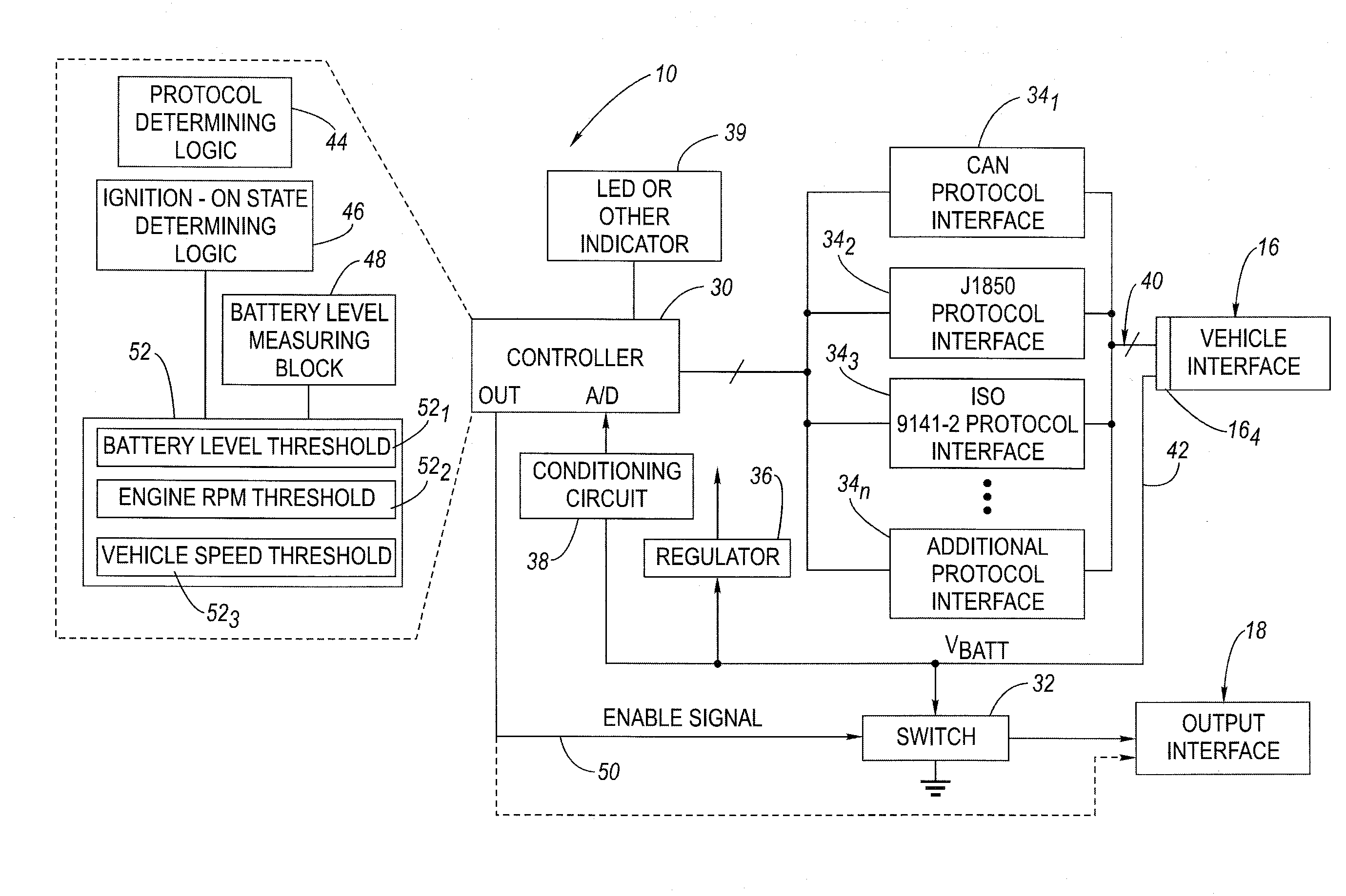
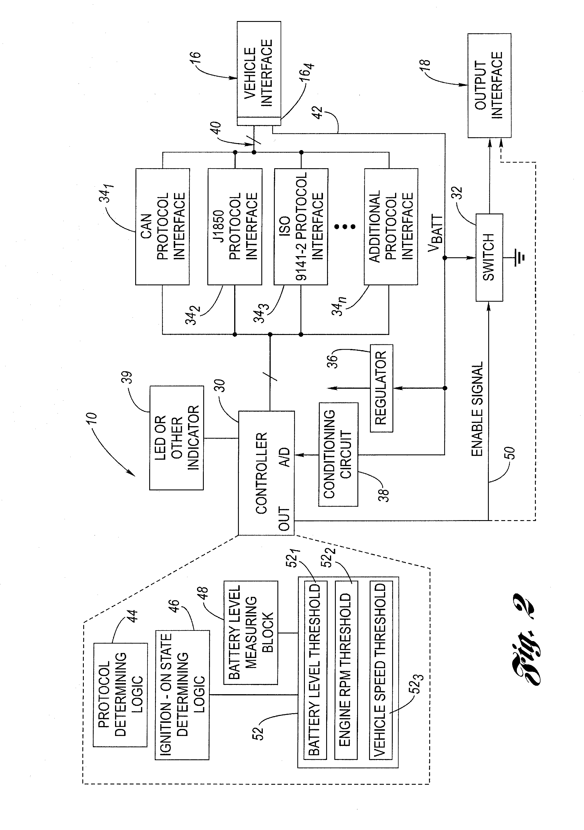
[0009]A power supply for use in a vehicle includes a vehicle interface and a controller. The vehicle interface is configured for connection to a vehicle diagnostic port, which in one embodiment may be an on-board diagnostic (OBD-II) compliant diagnostic port. The diagnostic port is configured to provide access to a vehicle network, which allows retrieval of stored diagnostic and vehicle operating data. The diagnostic port also provides un-switched vehicle power. The controller, which in one embodiment may be a programmed microcontroller, is configured to communicate via the vehicle interface through the vehicle diagnostic port to obtain current values for an engine speed parameter and a vehicle speed parameter. The controller is further configured to assert an enable control signal indicative of the operating state of the vehicle (“ignition-on state”) based on at least the engine speed and vehicle speed parameters.
[0010]As described above, the vehicle interface of the power supply is configured to receive a power signal (e.g., un-switched vehicle battery power) from the diagnostics port (e.g., OBD-II port) itself. The controller is further configured to determine whether to assert the enable control signal further as a function of the level of the power signal (e.g., assert the enable signal provided the power signal VBATT also meets or exceeds a predetermined minimum level).
[0011]The enable signal may be used as a trigger signal that can be provided to an external, trigger-operated power supply. In a preferred embodiment, the power supply further includes a switch configured to selectively switch or transfer the power signal from the diagnostic port to an output interface of the power supply based on whether the enable signal is asserted or not. This essentially emulates ignition-switched power as it goes on and off based on the operating (ignition) state of the vehicle. The output interface may comprise, in one embodiment, a standardized connector, such as an RJ-11 jack, to facilitate easy and rapid connection and disconnection of accessories to the inventive power supply.
[0012]A method is also presented for operating a power supply that is configured to emulate the functionality of ignition-switched power in a vehicle.

Problems solved by technology

However, some of the cigarette lighter plug arrangements are un-switched, meaning that the vehicle battery is unprotected against undesirable battery drain arising from electrical load that the accessory presents.
However, most consumers lack the necessary experience or tools needed to hard-wire an accessory device into their vehicle.
Hard wire approaches may impair one or both of these considerations.
Known in-vehicle powering approaches have not been entirely satisfactory, particularly for general powering use for a wide variety of accessory devices.
However, Plante et al. do not describe what is meant by prescribed type of traffic and in any event from the examples therein “in-use” does not appear wholly co-extensive with the ignition-on or ignition-off states.
Plante et al. does not provide for an external trigger or like mechanism to activate an external power supply or any other means to accommodate this situation.

Method used


Image

  • System and method for emulating vehicle ignition-switched power
  • System and method for emulating vehicle ignition-switched power
  • System and method for emulating vehicle ignition-switched power

Examples


Embodiment Construction

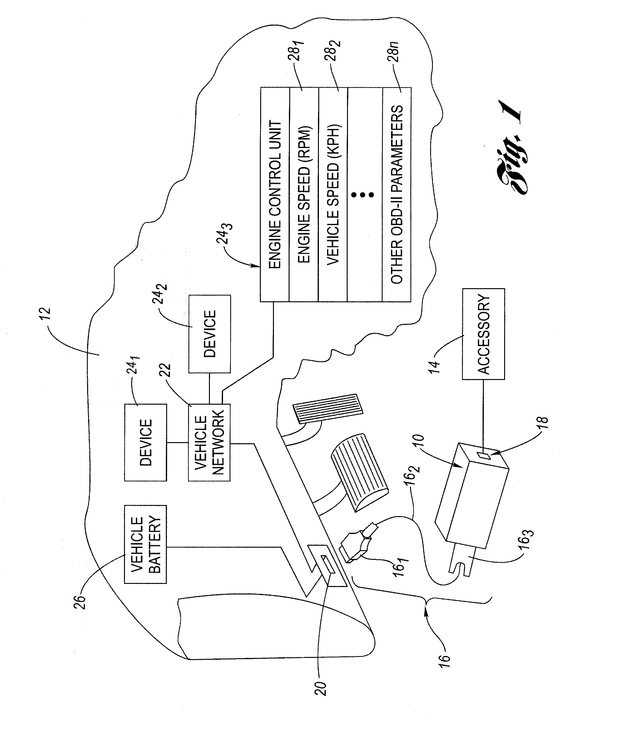
[0017]Referring now to the drawings wherein like reference numerals are used to identify identical components in the various views, FIG. 1 is a perspective view of a power supply 10 configured to emulate the functionality of ignition-switched power in a vehicle 12, an interior cabin portion of which is shown—partially broken away. The power supply 10 is operative to selectively provide power to an attached accessory 14 based on an operating state of the vehicle (i.e., an ignition-on state or an ignition-off state). Embodiments of the inventive power supply 10 allow it to be simply plugged into a vehicle diagnostics port (e.g., an OBD-II port; more on this below) to provide power to the accessory 14 that switches on and off to emulate an ignition-switched hard-wired connection. No tools or special connections are necessary. Installation is as simple as locating the vehicle diagnostics port and plugging in the power supply 10. Through the foregoing functionality, the accessory 14 can ...


PUM


Abstract

A power supply configured to emulate the functionality of ignition-switched power in a vehicle is configured to plug into an on-board diagnostics port (OBD-II) in the vehicle. The power supply includes a controller that is configured to determine the operating protocol to use and then communicates queries based on the determined protocol to obtain the current values for the engine speed and vehicle speed. The controller compares the current values against predetermined thresholds to determine whether the vehicle operating state is in an ignition-on state. When in the ignition-on state, the controller asserts an enable control signal, which is provided to a switch that responds by switching the un-switched vehicle battery from the OBD-II port to an output interface of the power supply. When the controller determines that the vehicle is no longer in an ignition-on state, the controller de-asserts the enable control signal, thereby removing the power from the output interface.

Description

CROSS-REFERENCE TO RELATED APPLICATIONS[0001]This application claims the priority benefit of U.S. Provisional Application No. 61 / 083,265 filed Jul. 24, 2008, the disclosure of which is hereby incorporated herein by reference in its entirety.BACKGROUND OF THE INVENTION[0002]1. Technical Field[0003]The present invention relates generally to power supply systems and more particularly to a system and method that emulates the functionality of vehicle ignition-switched power in a vehicle.[0004]2. Description of the Related Art[0005]Power for operating in-vehicle accessories, such as radar detectors, global positioning systems (GPS) navigation systems, cellular telephones, personal computers and the like have conventionally been provided through two mechanisms. The first mechanism involves the use of the well-known cigarette lighter plug. Many accessories are provided with a plug adapter that fits directly into the cigarette lighter. However, some of the cigarette lighter plug arrangements...

Claims


Application Information

Patent Timeline
IPC IPC(8): G06F7/00
CPCB60R16/03
Inventor HAMILTON, BRENNAN TODD
Owner HAMILTON PERFORMANCE ELECTRONICS
Learn More