
Steerable catheter and method of making the same

a technology of steerable coil and catheter, which is applied in the field of catheters, can solve the problems of product liability and medical malpractice lawsuits, the tip of the coil slipping, and the whole host of medical problems

Inactive Publication Date: 2010-01-28
NEUROTHERM
View PDF26 Cites 13 Cited by
  • Summary
  • Abstract
  • Description
  • Claims
  • Application Information

AI Technical Summary

Benefits of technology

[0010]These and other objects and advantages of the present invention will be readily appreciable from the following description of preferred embodiments of the invention and from the accompanying drawings and claims.

Problems solved by technology

One problem with prior coil catheters is that the tips have a tendency to detach from the coil while the catheter is still inserted within a patient.
This can lead to whole host of medical problems, as well as product liability and medical malpractice lawsuits.
Often, a tip detaches because the means for affixing it to the end of the coil is inadequate, due to the general inability to assemble and connect such small components.
This problem is exacerbated when the attached tip has a diameter greater than the diameter of the coil, as the oversized tip tends to get caught on tissue, which can lead to tissue damage during operation, and on the end of the introducers used to provide the catheter access into the target tissue and epidural space.
Another problem with prior coil catheters is that they are difficult to direct after they have been inserted into the target area.
This drawback prevents a user from steering the catheter in and around structures, such as, spinal nerves and bone processes, which limits his ability to effectively reach target tissues he wishes to expose to drugs, such as, anti-inflammatories, steroids, analgesics, etc.

Method used


Image

  • Steerable catheter and method of making the same
  • Steerable catheter and method of making the same
  • Steerable catheter and method of making the same

Examples


Embodiment Construction

[0019]At the outset, it should be appreciated that like drawing numbers on different drawing views identify identical, or functionally similar, structural elements of the invention. While the present invention is described with respect to what is presently considered to be the preferred aspects, it is to be understood that the invention as claimed is not limited to the disclosed aspects.

[0020]Furthermore, it is understood that this invention is not limited to the particular methodology, materials and modifications described and as such may, of course, vary. It is also understood that the terminology used herein is for the purpose of describing particular aspects only, and is not intended to limit the scope of the present invention, which is limited only by the appended claims.

[0021]Unless defined otherwise, all technical and scientific terms used herein have the same meaning as commonly understood to one of ordinary skill in the art to which this invention belongs. Although any meth...


PUM

PropertyMeasurementUnit
angleaaaaaaaaaa
outer diameteraaaaaaaaaa
inner diameteraaaaaaaaaa

Abstract

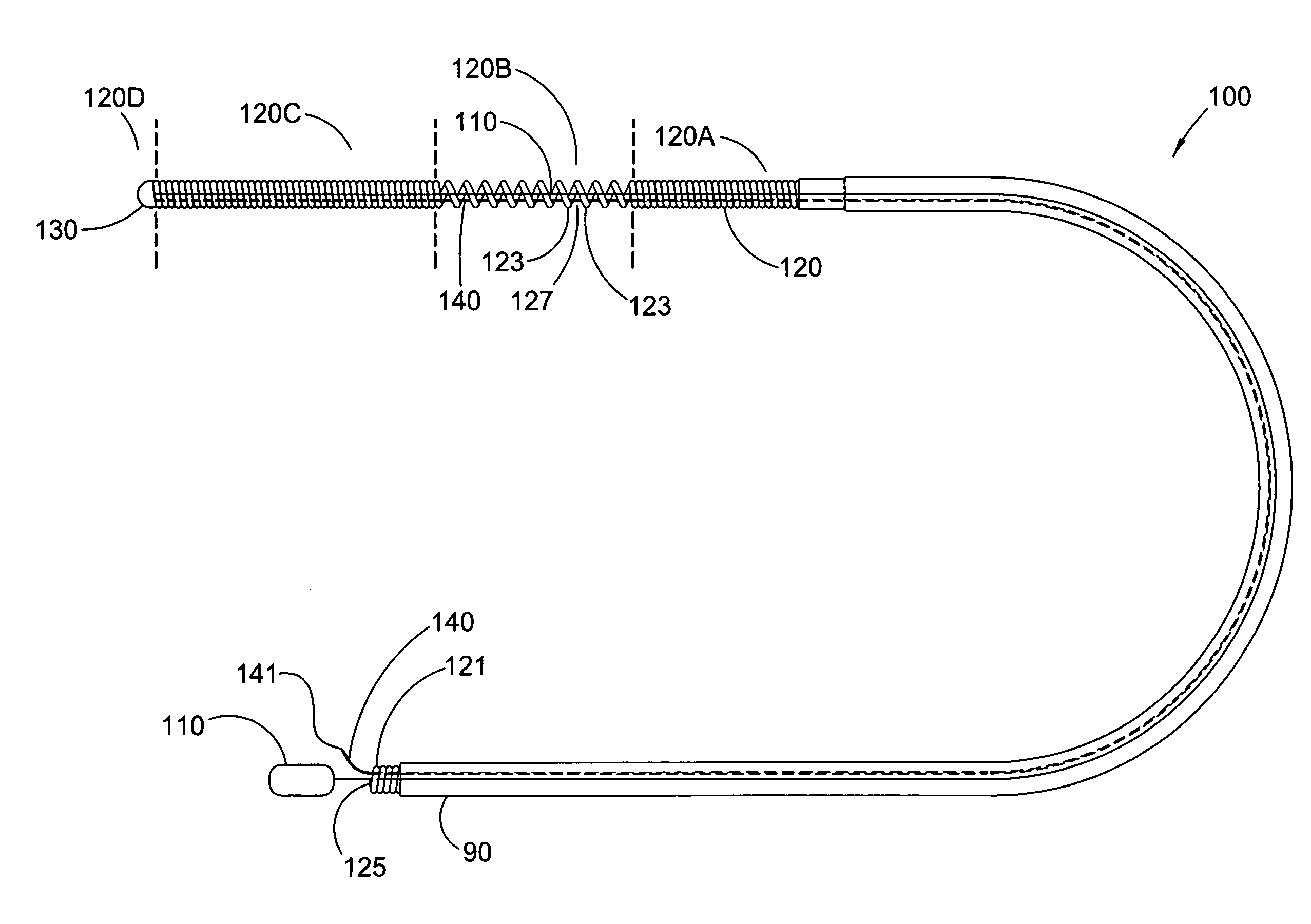
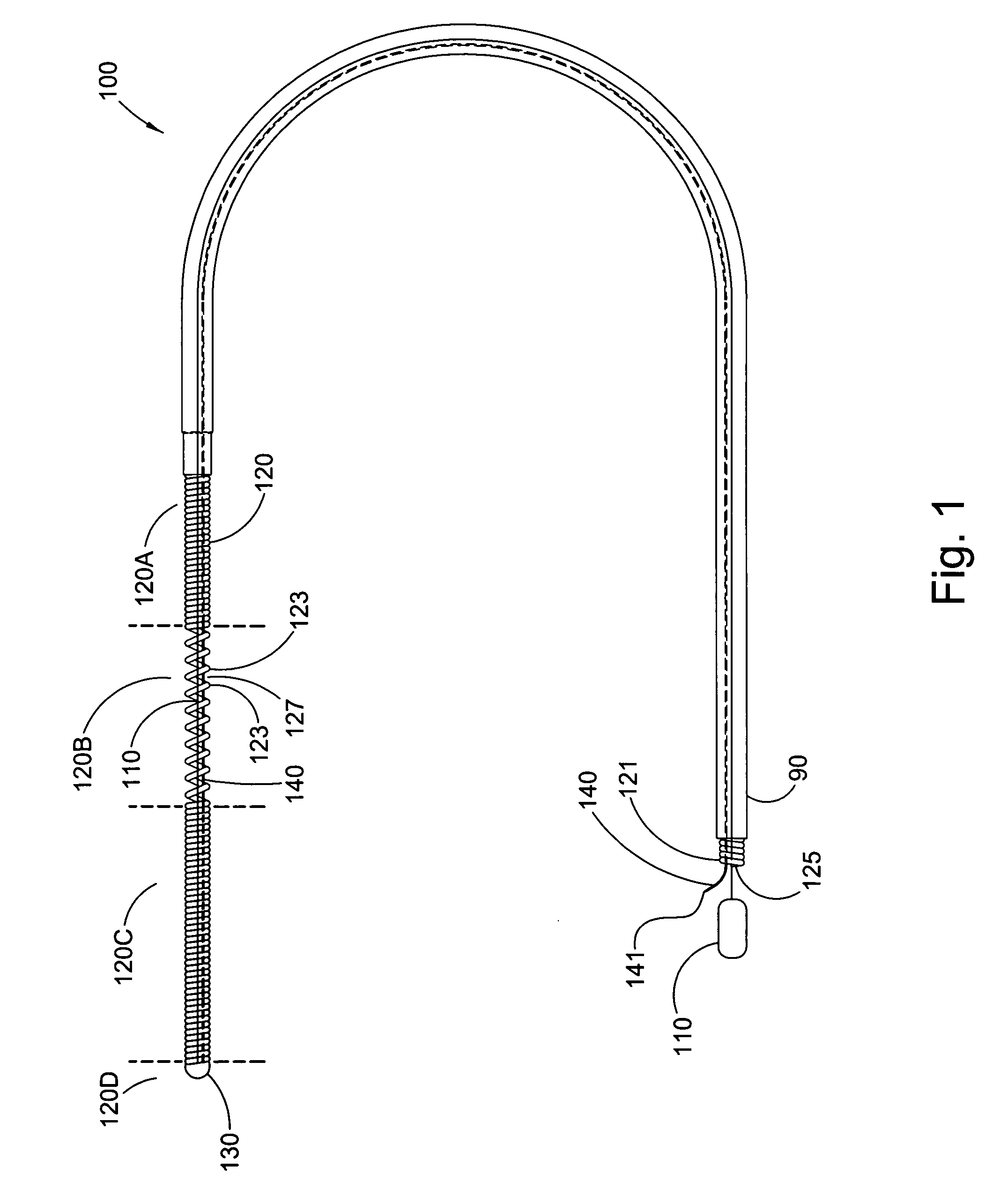
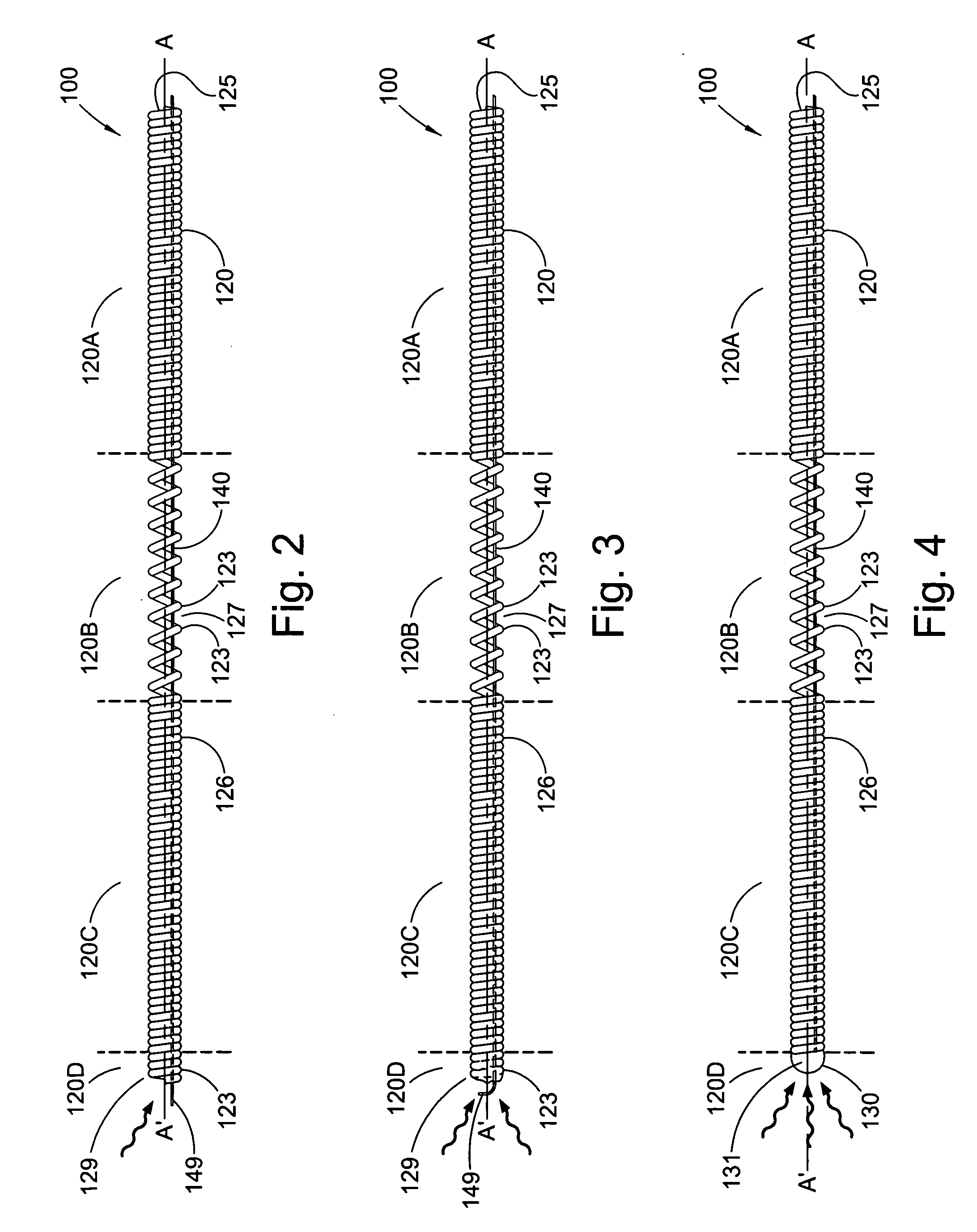
A steerable catheter including a helical coil of wire having a longitudinal axis, a distal end, a proximal end, and a lumen extending longitudinally from the distal end to the proximal end, a ribbon having a distal end, and extending longitudinally, adjacent to the longitudinal axis, within the lumen, from the distal end of the helical coil to the proximal end of the helical coil, and a tip formed by a laser-welded fusion of the distal end of the helical coil and the distal end of the ribbon, the tip being arranged to close the distal end of the helical coil, and operatively arranged to move in a first direction away from the longitudinal axis when the ribbon is forced in a first longitudinal direction, and move in a second direction away from the longitudinal axis when the ribbon is forced in a second longitudinal direction.

Description

FIELD OF THE INVENTION[0001]The invention broadly relates to catheters. More particularly, the invention relates to coil catheters and, even more particularly to steerable coil catheters.BACKGROUND OF THE INVENTION[0002]Coil catheters are well known and commonly used, particularly for epidural injections. Generally, a coil catheter comprises a stainless steel, helical coil having a lumen, and a plurality of openings near its distal end for delivering drugs into the surrounding space and tissues. Commonly, its distal end is closed via a tip assembly comprising an initially separate tip that is fixed to the distal end of the coil via some type of adhesive or welding.[0003]One problem with prior coil catheters is that the tips have a tendency to detach from the coil while the catheter is still inserted within a patient. This can lead to whole host of medical problems, as well as product liability and medical malpractice lawsuits. Often, a tip detaches because the means for affixing it ...

Claims


Application Information

Patent Timeline
Patent Type & Authority Applications(United States)
IPC IPC(8): A61M25/01C21D1/40
CPCA61M25/001A61M25/0147A61M25/0138A61M25/0012
Inventor PARASMO, RONALD S.RENICK, MICHAEL A.
Owner NEUROTHERM
Learn More