Heating cooker

a cooker and heating technology, applied in the field of heating cookers, can solve the problems of confusion, user cannot recognize which operation takes the highest priority, and specific information may be lost, and achieve the effect of more user-friendly operation guiding

Active Publication Date: 2010-01-28
PANASONIC CORP
View PDF9 Cites 12 Cited by
  • Summary
  • Abstract
  • Description
  • Claims
  • Application Information

AI Technical Summary

Benefits of technology

[0035]Because operable operation units are lit, the user can visually identify the operation units. Among those operation units, only the operation unit having higher priority is lit in a different color. This structure can provide more user-friendly operation guiding.

Problems solved by technology

In another case, the specifications may be lost.
However, the conventional structure has the following problems.
However, in this case, the alarm sound suggests the notification of the cases other than erroneous operation, such as a failure, the sound of a timer, and confuses the user.
However, when a plurality of operations is selectable in the next step, the user cannot recognize which operation takes the highest priority.
Further, when only one operating body light-emitting element is lit for operation guiding, the other operable functions cannot be indicated.[Patent Document 1] Japanese Patent Unexamined Publication No. 2001-51777

Method used


Image

  • Heating cooker
  • Heating cooker
  • Heating cooker

Examples


first exemplary embodiment

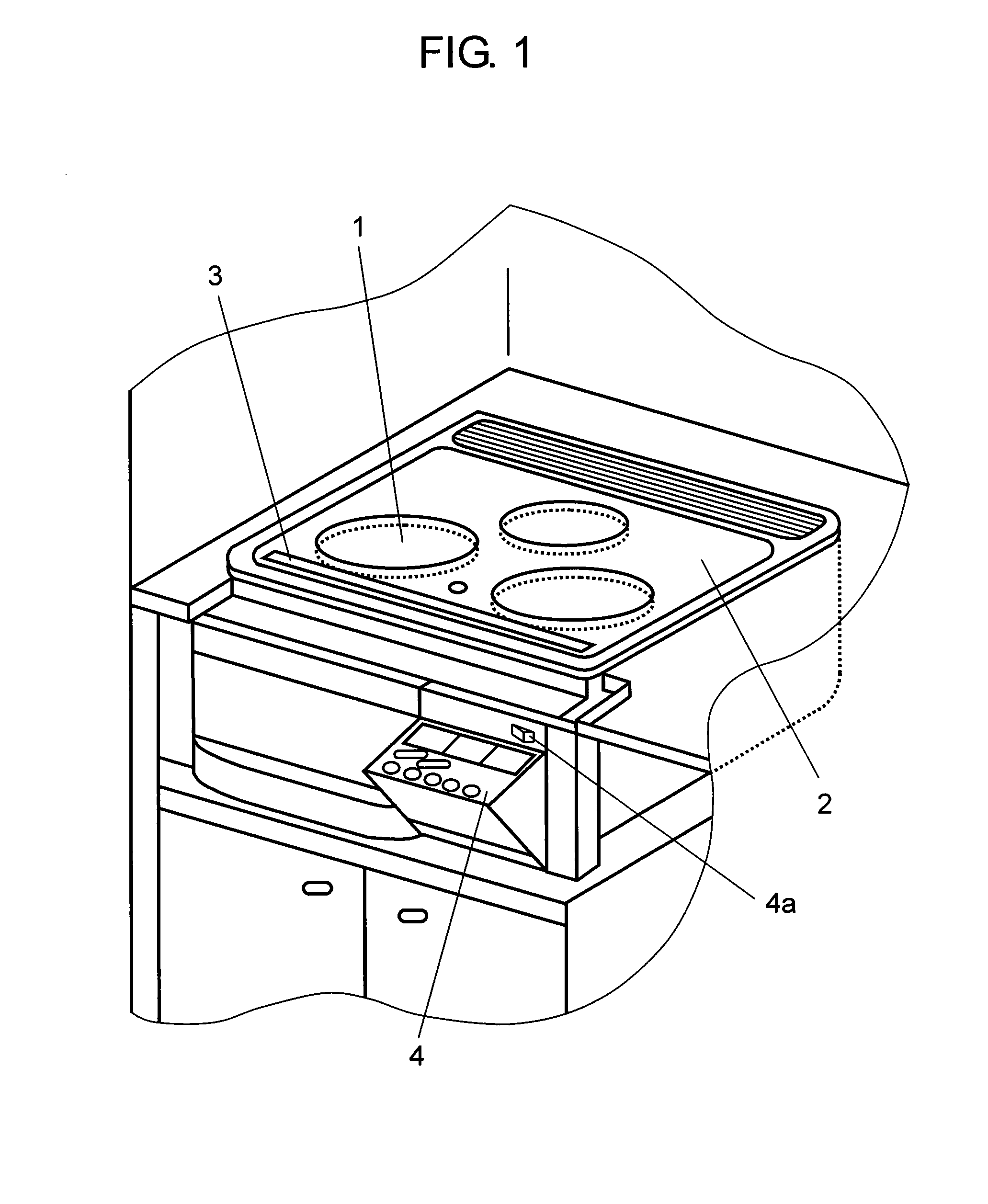
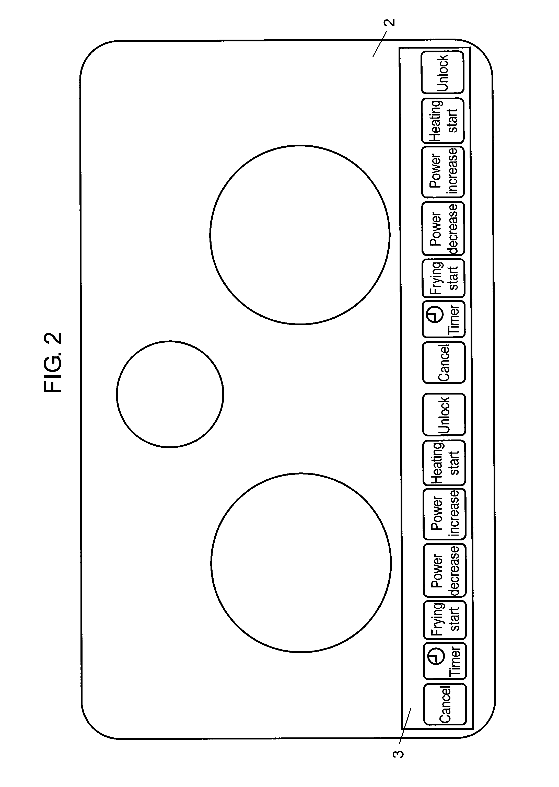
[0109]FIG. 1 is an outside view showing a heating cooker in accordance with the first exemplary embodiment of the present invention. With reference to FIG. 1, the major components of this heating cooker are as follows: top plate 2 that is provided on the top face of the appliance to receive an object to be heated (not shown) thereon, and formed of a highly heat-resistant, electrically-insulating material, such as a heat-resistant glass made of an optically-transparent crystallized ceramic, into a planar shape; heating unit 1 formed in top plate 2; top-face operation unit 3 formed in top plate 2 on the front side of heating unit 1; and kangaroo-type operation unit 4 that is placed on the front side of the heating cooker and can be advanced and retracted.

[0110]In the area of top-face operation unit 3, electrostatic touch keys 5 each for instructing execution of a function assigned thereto are formed. Each electrostatic touch key 5 has electrode 5b formed of a light-blocking conductive...

second exemplary embodiment

[0152]The second exemplary embodiment of the present invention has a primary appearance and structure similar to those shown in FIGS. 1 through 3. FIGS. 1 through 3 are also used for this exemplary embodiment, and the detailed descriptions of the appearance and structure are omitted.

[0153]FIG. 6A is a top view showing a state in which all the light-guiding plates 7 are lit in a part of top-face operation unit 3 of a heating cooker in accordance with the second exemplary embodiment. FIG. 6B is a top view showing a state in which one of light-guiding plates 7 is lit in a relatively short cycle (of 0.5 sec). FIG. 6C is a top view showing a state in which one of light-guiding plates 7 is flashed in a predetermined relatively short cycle (of 0.5 sec), and another one of light-guiding plates 7 is flashed in a predetermined relatively long cycle (of 1.0 sec).

[0154]Electrostatic touch keys 11aa through 11gg show electrostatic touch keys 5 corresponding to respective functions.

[0155]Specific...


PUM


Abstract

Operability of a heating cooker having a heating unit in a top plate is improved. After power-on, a light emission control unit causes the operation unit light-emitting element of an operable operation inhibition releasing key to be lit so that only the key is displayed and the other keys are less visible. Thus, the heating cooker is changed into a lock state. When the operation inhibition releasing key is operated in the lock state, at least one electrostatic touch key other than the operation inhibition releasing key is made operable and the operation unit light-emitting element is lit. Alternatively, in the above structure, the operation unit light-emitting element of the operable operation unit is lit in a first light-emission color, and the operation unit light-emitting elements of the inoperable operation units are lit in a second light-emission color different from the first light-emission color. Thus effective operation can be guided.

Description

TECHNICAL FIELD[0001]The present invention relates to a heating cooker in which operation units thereof are lit.BACKGROUND ART[0002]A block structural diagram of such a type of conventional electronic appliance 100 is shown in FIG. 8. As shown in FIG. 8, electronic appliance 100 has data bus 101. Storage unit 102 is connected to this data bus 101. The storage unit stores operation guiding information substantially covering the specifications of electronic appliance 100. Operation guiding information is prepared for the operating procedures predetermined for electronic appliance 100.[0003]Storage unit 102 is formed of a read-only memory (ROM). To this storage unit 102, display unit 103 is connected via data bus 101. The operation guiding information read from storage unit 102 is displayed on display unit 103.[0004]Selecting unit 104 is connected to this display unit 103 via data bus 101. When a user selects an operation guiding mode with mode selecting unit 109, options for selecting...

Claims


Application Information

Patent Timeline
Patent Type & Authority Applications(United States)
IPC IPC(8): G09F13/08H03K17/96
CPCF24C7/086
Inventor ISODA, KEIKONAGATA, RYUUJISATOU, CHIKASHIINADA, TSUYOSHI
Owner PANASONIC CORP
Why Eureka
Try Eureka