
High voltage bushing

Active Publication Date: 2010-01-28
HITACHI ENERGY SWITZERLAND AG
View PDF10 Cites 16 Cited by
  • Summary
  • Abstract
  • Description
  • Claims
  • Application Information

AI Technical Summary

Benefits of technology

[0008]An object of the present invention is to provide a high voltage bushing and a method of manufacturing the same, wherein the manufacturing and handling of the bushing is simplified compared to prior art bushings.
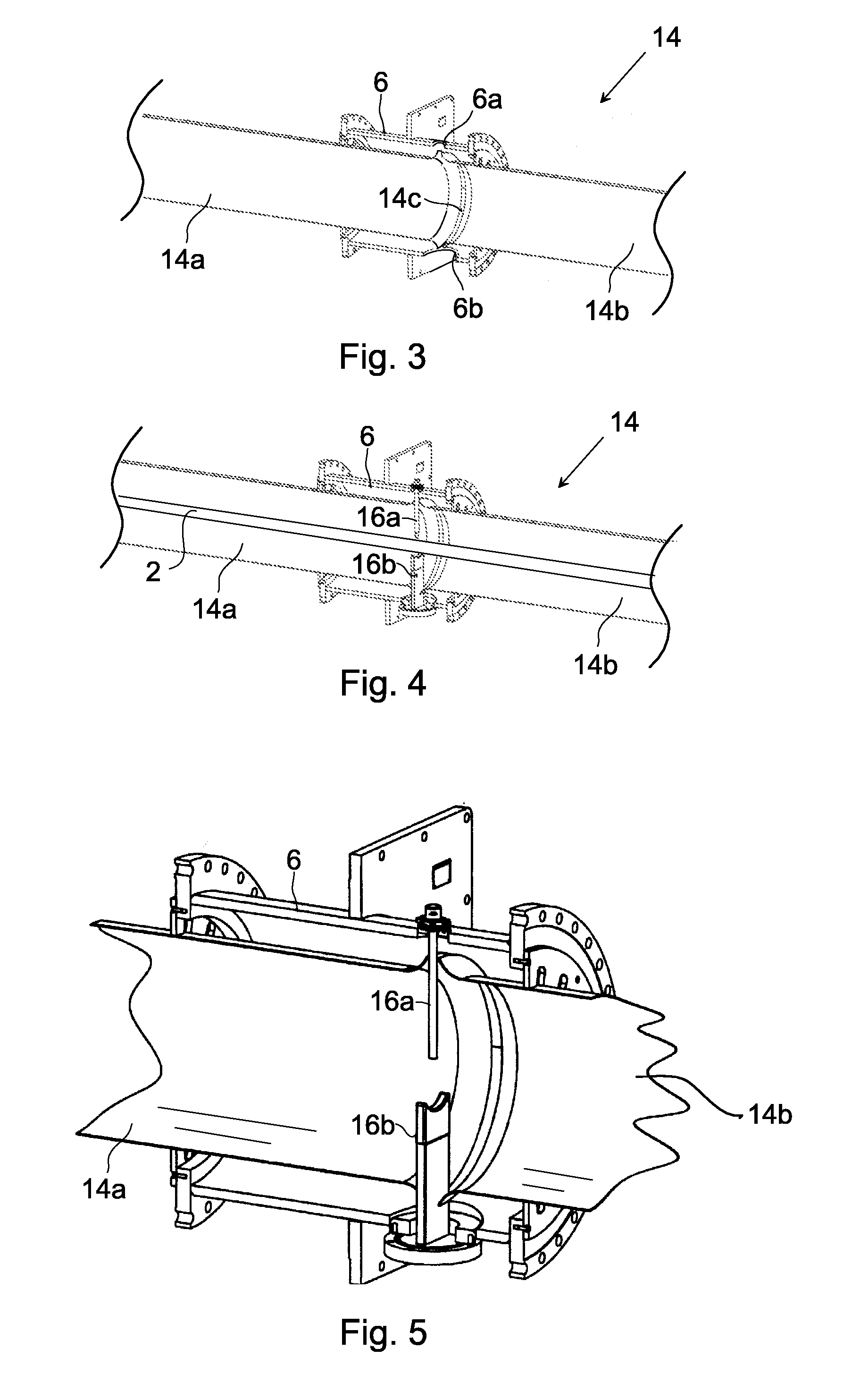
[0012]With the inventive bushing, several advantages are obtained. By providing a voltage grading shield in two or more parts, the high voltage bushing is easier to manufacture since each part is only about half the size of what it would be as a one piece shield. Also, the reduced sized of the shield parts makes the voltage grading shield easier to handle and store.
[0013]In a preferred embodiment, there is a gap between the first and second shield parts. This allows for a dielectrically advantageous design of the end edges of the shield parts. This includes avoiding holes in the voltage grading shield provided for a support for the high voltage conductor used during transportation.
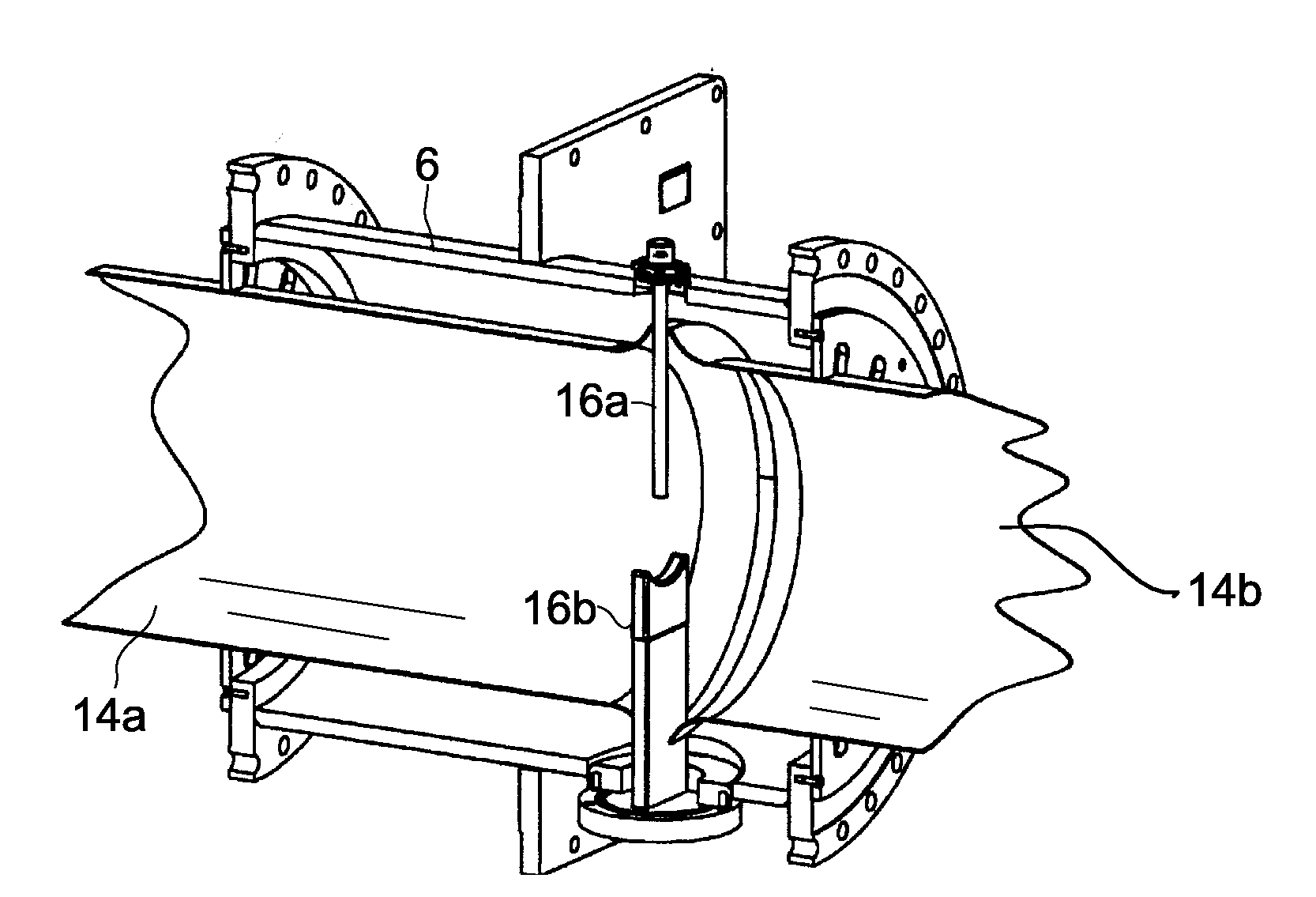
[0015]In a preferred embodiment, the wall flange comprises two holes diametrically opposite to each other and aligned with the shield gap, wherein a transport support for the high voltage conductor is provided in the holes. This provides for a simple and yet reliable transport support for the conductor. If the transport support comprises a pin and a recessed part between which the conductor is clamped, unwanted horizontal and vertical movement of the conductor is prevented during transportation of the bushing.

Problems solved by technology

In high voltage applications, the voltage grading shield can be very large, such as five meters or more in length, which complicates manufacturing and transportation of the bushing.

Method used


Image

  • High voltage bushing
  • High voltage bushing
  • High voltage bushing

Examples


Embodiment Construction

[0023]In the following a detailed description of a preferred embodiment of the present invention will be given. In this description, the term “high voltage” will be used for voltages of 10 kV and higher. Today, the upper limit in commercial high voltage devices is 800 kV but even higher voltages, such as 1000 kV or more, are already built or envisaged in the near future.

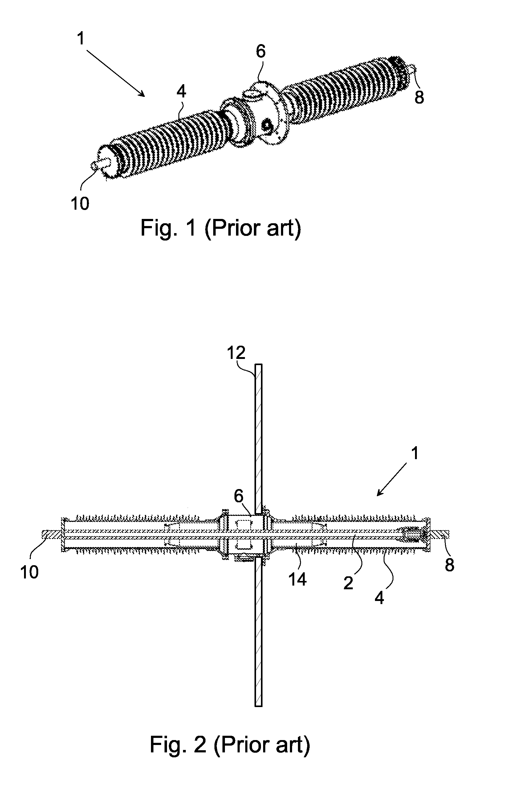
[0024]The present invention is applicable to the general description of the high voltage bushing given in the background section with reference to FIGS. 1 and 2 and reference will in the following be made to these figures. However, reference will first be made to FIG. 3, showing a partially cut-away perspective view of a voltage grading shield 14, including a wall flange 6, for a bushing according to the invention.

[0025]The voltage grading shield 14 comprises two separate shield parts, a first part 14a and a second part 14b. The two shield parts are separated by a gap 14c, which is symmetrical about the center axis o...


PUM

PropertyMeasurementUnit
Electric potential / voltageaaaaaaaaaa

Abstract

A high voltage bushing including a voltage grading shield in two parts.

Description

FIELD OF INVENTION[0001]The present invention relates generally to high voltage bushings and more particularly to a high voltage bushing with simplified manufacturing. The invention also relates to a device comprising such bushing and a method of manufacturing a high voltage bushing.BACKGROUND[0002]It is known that electrical equipment and devices, such as high voltage transformers, are usually equipped with bushings, which are suitable to carry current at high potential through a grounded barrier, e.g. a transformer tank or a wall.[0003]Conventional bushings are constituted by an insulator made of ceramic or composite material, which is provided with sheds and is generally hollow. The voltage grading can be obtained with or without a condenser body through which the electrical conductor passes.[0004]An example of a bushing 1 for wall mounting will now be described with reference to FIG. 1 showing the overall structure of the bushing, and FIG. 2 showing a sectional view of the bushi...

Claims


Application Information

Patent Timeline
IPC IPC(8): H01T4/14B23P11/00
CPCY10T29/49826H01B17/42H01B17/26
Inventor EMILSSON, DAVIDERIKSSON, THOMAS
Owner HITACHI ENERGY SWITZERLAND AG
Learn More