
Viv and/or drag reduction device installation systems and methods

a technology of drag reduction device and installation system, which is applied in waterborne vessels, construction, foundation engineering, etc., can solve the problems of large vibration transverse to current, unacceptably short fatigue life, and substantial vibration of structural elements, and achieve the effect of fewer trips

Inactive Publication Date: 2010-01-21
SHELL OIL CO
View PDF3 Cites 1 Cited by
  • Summary
  • Abstract
  • Description
  • Claims
  • Application Information

AI Technical Summary

Benefits of technology

[0017]Another aspect of the invention provides a method comprising moving a transport tool carrying a plurality of VIV and / or drag reduction devices near to the structural element; moving an installation tool near to the transport tool; removing one or more VIV and / or drag reduction devices from the transport tool to the installation tool; and installing the one or more VIV and / or drag reduction devices around the structural element with the installation tool.
[0018]Advantages of the invention include one or more of the following:
[0019]an improved apparatus and method for installing VIV and / or drag reduction devices;
[0020]an apparatus for and new and improved methods of installing VIV and / or drag reduction devices in a flowing fluid environment;
[0021]an apparatus for and new and improved methods of installing VIV and / or drag reduction devices with fewer trips required to the surface for additional devices; and
[0022]an apparatus for and new and improved methods of installing VIV and / or drag reduction devices which does not require retrieving the tooling to the surface to reload the tooling with additional devices.

Problems solved by technology

These vibrations may be caused by oscillating dynamic forces on the surface which can cause substantial vibrations of the structural element, especially if the forcing frequency is at or near a structural natural frequency.
If the frequency of this harmonic load is near the resonant frequency of the structural element, large vibrations transverse to the current can occur.
These vibrations can, depending on the stiffness and the strength of the structural element and any welds, lead to unacceptably short fatigue lives.
In fact, stresses caused by high current conditions in marine environments have been known to cause structural elements such as risers to break apart and fall to the ocean floor.
For instance, a riser pipe that is vibrating due to vortex shedding will disrupt the flow of water around it more than a stationary riser.
This may result in more energy transfer from the current to the riser, and hence more drag.
Deploying structural elements may damage the VIV and / or drag reduction devices by the installation, for example by the stinger or rollers during an S-lay installation.
A pre-installed VIV and / or drag reduction devices may be damaged if it passes over the stinger.
In addition, holding onto a structural element with a tensioner may damage VIV and / or drag reduction devices.
In addition, VIV and / or drag reduction devices may have a useful life less than the life of the structural element to which they have been applied.
Currently, the number of devices that can be transported to the desired depth and location is limited, and may lead to increased costs and installation time to transport additional devices to the desired depth and location.

Method used


Image

  • Viv and/or drag reduction device installation systems and methods
  • Viv and/or drag reduction device installation systems and methods
  • Viv and/or drag reduction device installation systems and methods

Examples


Embodiment Construction

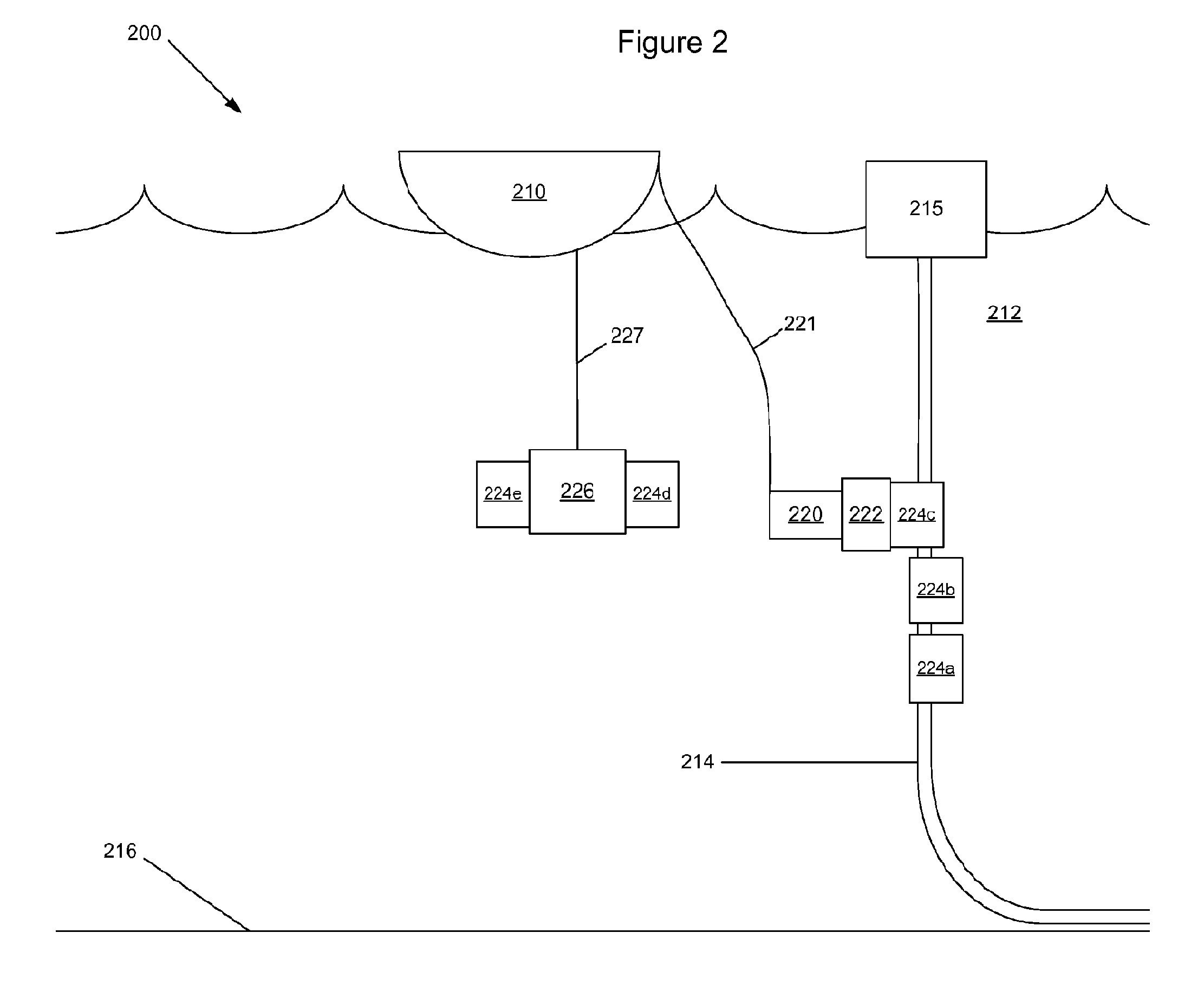
[0028]Referring now to FIG. 2, in one embodiment of the invention, system 200 is illustrated. System 200 includes vessel 210 in body of water 212, installing VIV and / or drag reduction devices 224a-224e, for example strakes or fairings, on structural element 214. As shown, structural element 214 may be a riser, tendon, connector, tubular, umbilical, or other structural or fluid transportation member, and may be connected to surface structure 215. Remotely operated vehicle (ROV) 220 is connected by umbilical 221 to vessel 210. ROV 220 is also connected to installation tool 222, to install VIV and / or drag reduction device 224c on structural element 214. Transport tool 226 is connected by line 227 to vessel 210. In some embodiments, line 227 may be an umbilical, a rope, a cable, a wire, or others as are known in the art. Transport tool is used to transport VIV and / or drag reduction devices 224d and 224e from vessel 210 to near desired location of structural element 214.

[0029]In some emb...


PUM


Abstract

There is disclosed a system comprising a structural element; a transport tool carrying a plurality of VIV and / or drag reduction devices; and an installation tool adapted to remove a VIV and / or drag reduction device from the transport tool and to install the device around the structural element.

Description

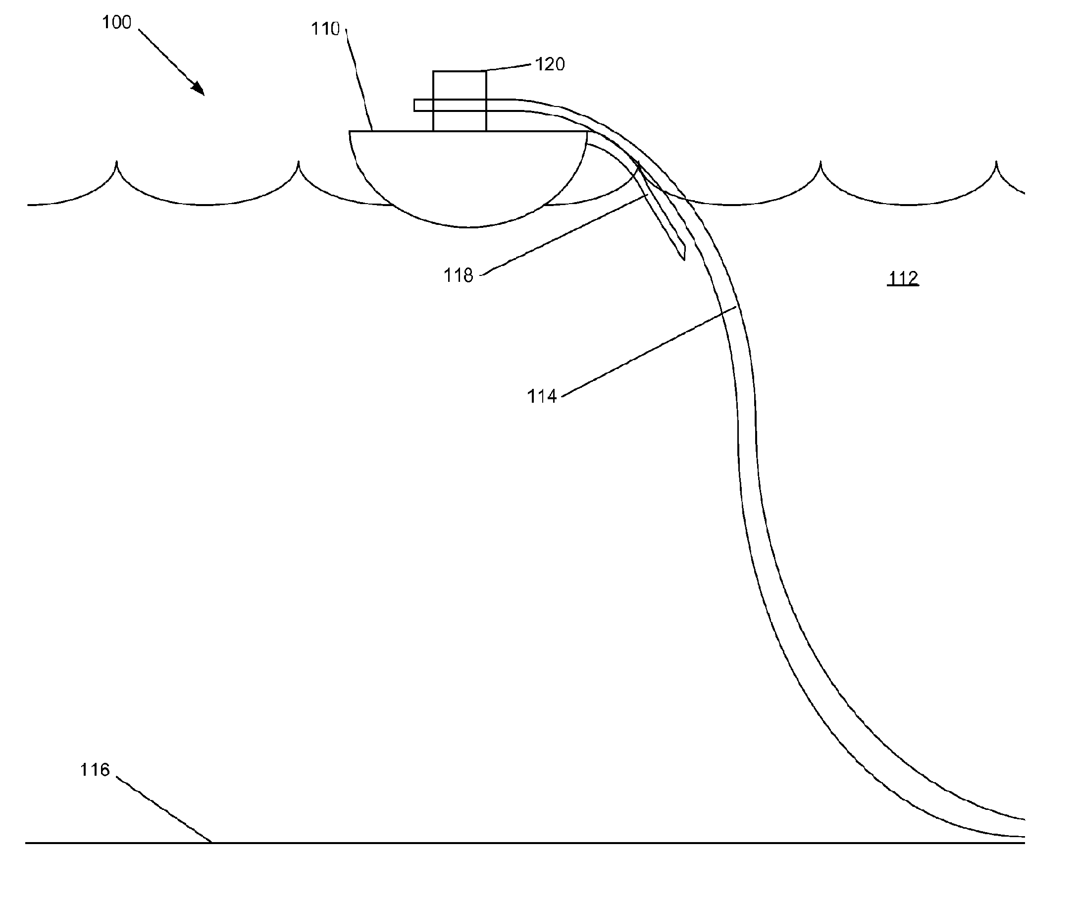
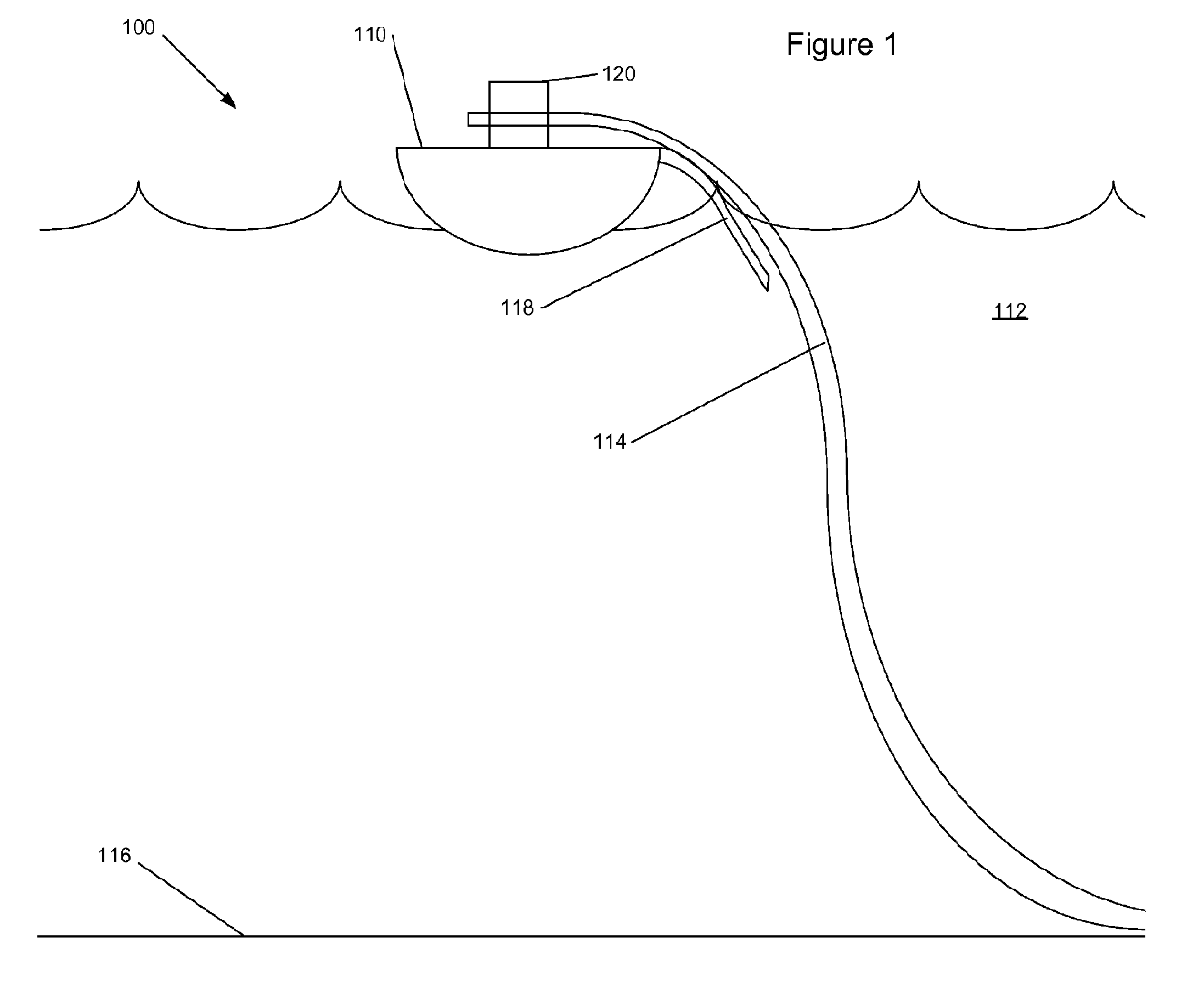
FIELD OF INVENTION[0001]The present disclosure relates to VIV and / or drag reduction device installation systems and methods. In particular to installation systems and methods for use underwater.BACKGROUND[0002]Structural elements can be installed at sea from a floating vessel using a J-lay configuration where the structural element is held vertically on the vessel and dropped vertically into the water and then when it reaches the bottom of the body of water, it lays horizontal, or alternatively structural elements can be installed in a S-lay configuration where the structural element is held horizontally on the vessel, drops to vertical through the body of water, and then rests on the bottom of the body of water in a horizontal configuration. Other configurations for installing a structural element from a vessel in a body of water are also known.[0003]Referring now to FIG. 1, system 100 for installing structural element 114 on bottom 116 of body of water 112 is illustrated. System 1...

Claims


Application Information

Patent Timeline
Patent Type & Authority Applications(United States)
IPC IPC(8): E02D5/60
CPCB63B2021/504B63B21/502E21B17/01
Inventor ALLEN, DONALD WAYNEARMSTRONG, STEPHEN PAULHENNING, DEAN LEROY
Owner SHELL OIL CO
Learn More