
Winds aloft profiling system

Inactive Publication Date: 2010-01-21
HONEYWELL INT INC
View PDF21 Cites 10 Cited by
  • Summary
  • Abstract
  • Description
  • Claims
  • Application Information

AI Technical Summary

Benefits of technology

[0009]The LDV can assess the velocity of wind by ascertaining the velocity vector of motes within the flow of wind. LDV systems provide wind speed data by measuring the Doppler shift imparted to laser light that is scattered from natural aerosols (e.g. dust, pollen, water droplets etc.) present in air. LDV systems measure the Doppler shift imparted to reflected radiation within a certain remote probe volume and can thus only acquire wind velocity data in a direction parallel to the transmitted laser beam. In the case of a LDV device located on the ground, it is possible to measure the true (3D) wind velocity vector a given distance above the ground by scanning the LDV in a controlled manner; for example using a conical scan. This enables the wind vector to be intersected at a range of known angles thereby allowing the true wind velocity vector to be constructed.

Problems solved by technology

As the hotter air rises admitting the colder air to the area near the ground, additional and complex air flows are generated.
Turbulence is very dangerous to skydivers because if a jumper gets caught in a downward flow of air, it will accelerate the parachutist toward the ground, which can result in injury or death.
The differential between time under the canopy and time in freefall can also make the prediction of a landing site even more difficult.
At that, the results are generally less exact than would be desired.
In many instances, contact with a ground party is not possible or at least, not desirable.
In relief operations after natural disasters, rapid, accurate drops of supplies cannot be reliably coordinated given the compromised infrastructure that may then exist.

Method used


Image

  • Winds aloft profiling system
  • Winds aloft profiling system
  • Winds aloft profiling system

Examples


Embodiment Construction

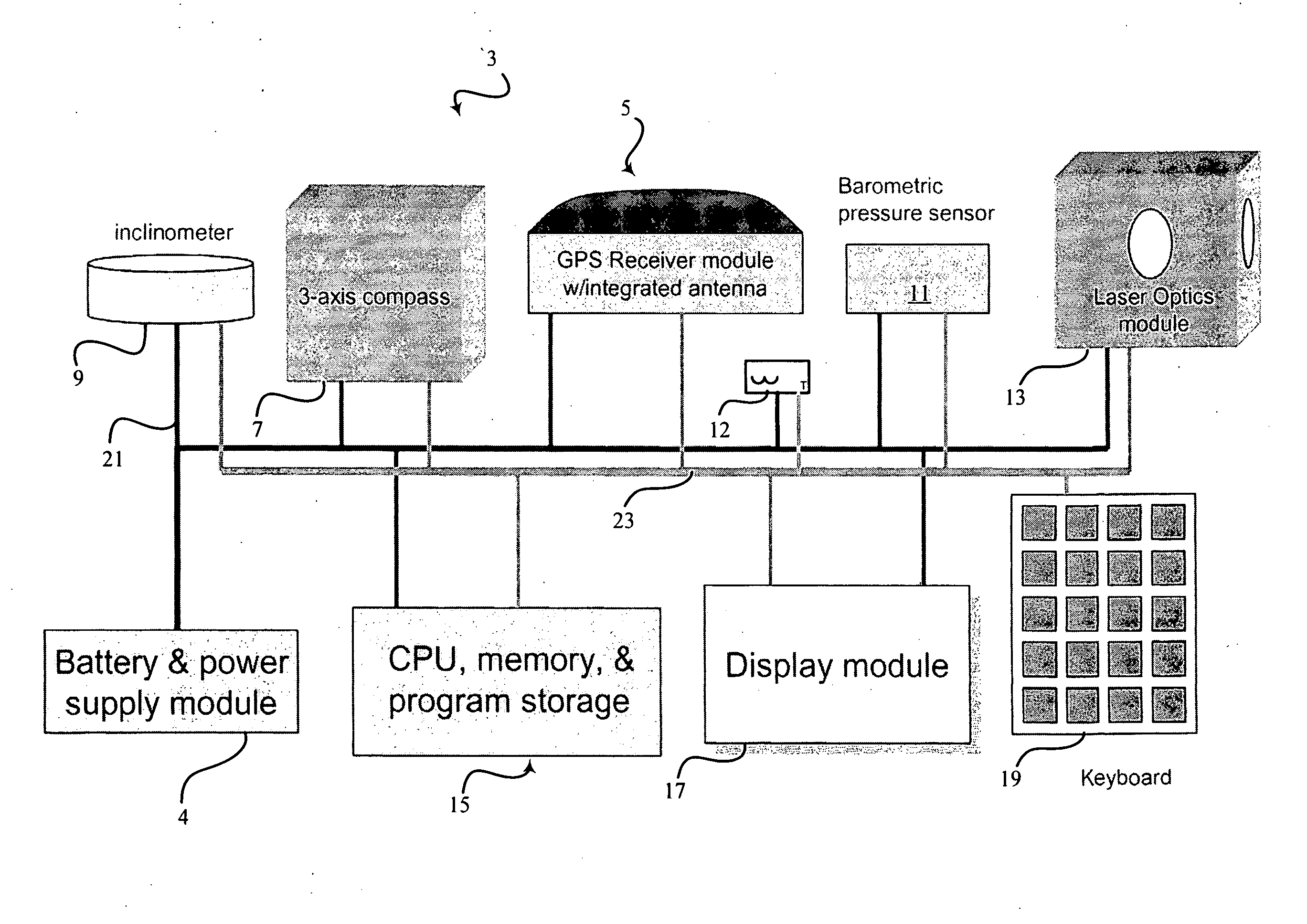
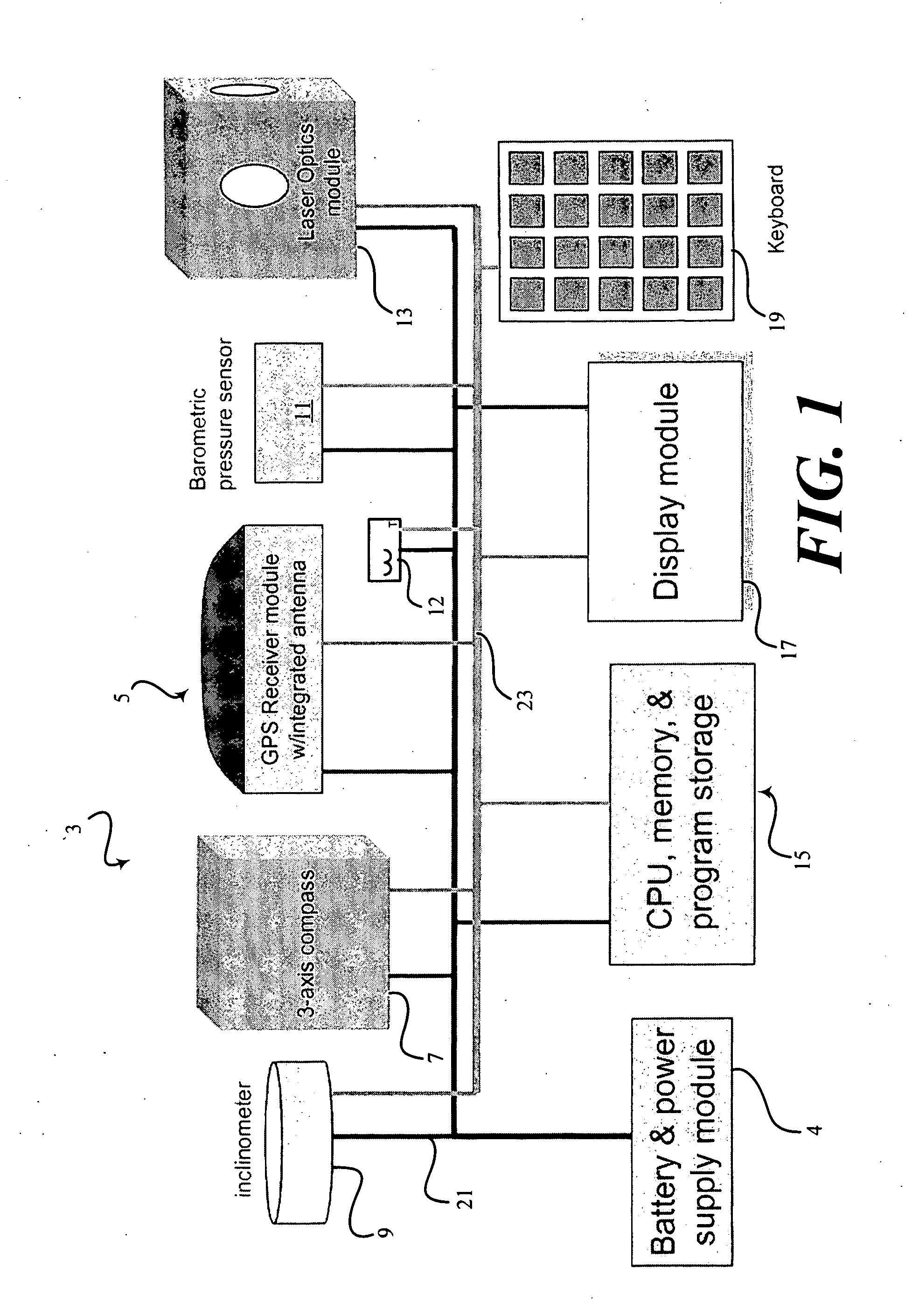
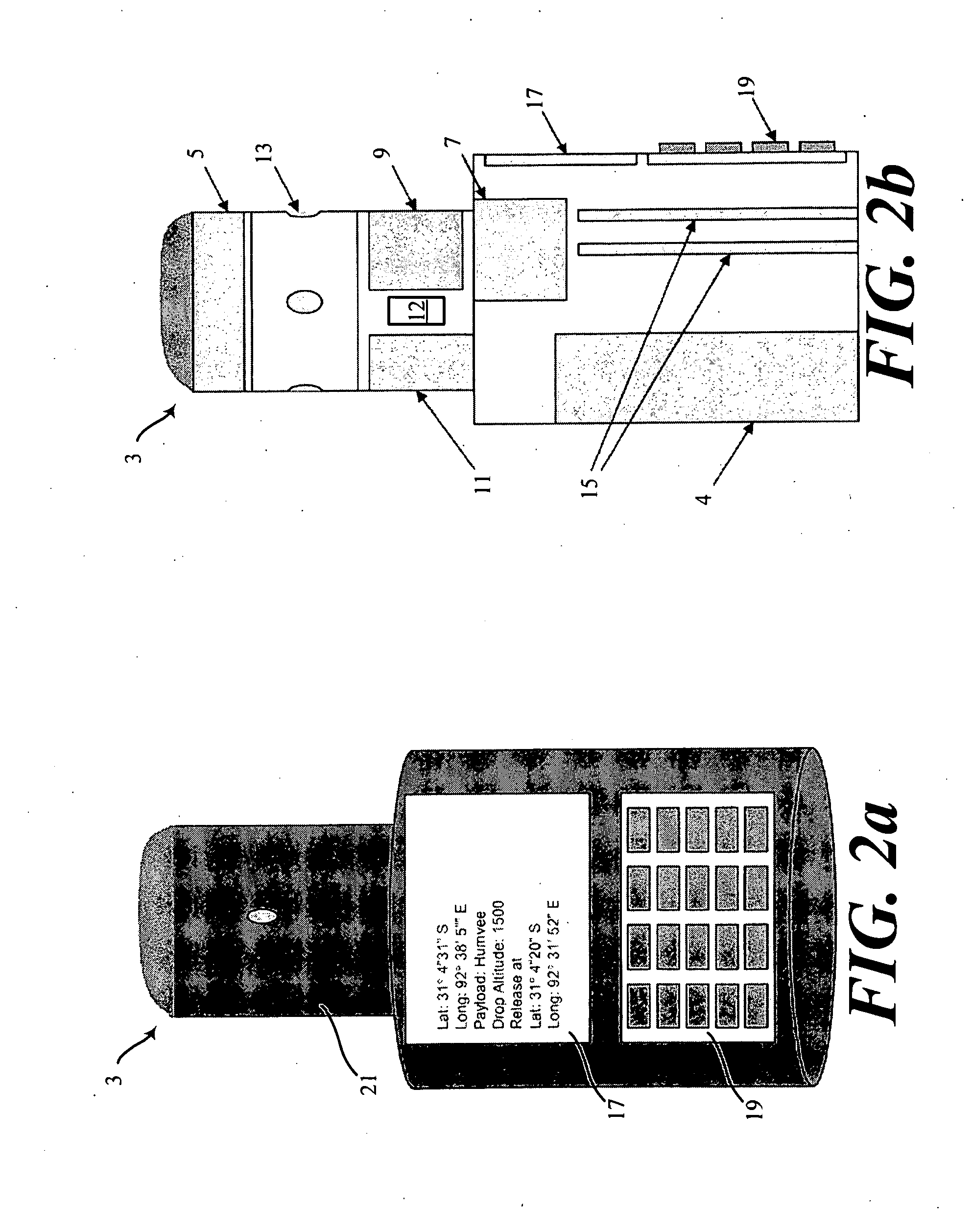
[0018]A handheld, portable wind profiler for winds aloft includes a system bus for receiving a GPS signal including a time and position solution and a three-axis magnetic compass for determining magnetic north relative to the orientation of the winds aloft profiler and an 2-axis inclinometer to provide a level reference plane regardless of inclination of the device. An optical module includes at least one laser Doppler velocimeter including an mount allowing the at least one laser Doppler velocimeter to articulate in at least two axes, thereby to orient the laser Doppler velocimeter above the horizon to generate at least one first velocimeter signal. The velocimeter signal includes at least one first radial velocity of a first wind-borne aerosol and a first orientation of the at least one laser Doppler velocimeter relative to the ground. A processor module receives the first velocimeter signal at the time from at least one laser Doppler velocimeter.

[0019]As illustrated in FIG. 1, an...


PUM


Abstract

An airborne wind profiler for an aloft aircraft includes a system bus for receiving a GPS signal including a time and position solution and an attitude signal representing heading, roll, pitch, and yaw of the aircraft. An optical module includes at least one laser Doppler velocimer including an mount allowing the at least one laser Doppler velocimeter to articulate in at least two axes, thereby to orient the laser Doppler velocimeter below a horizon to generate at least one first velocimeter signal. The velocimeter signal includes at least one first radial velocity of a first wind-borne aerosol and a first orientation of the at least one laser Doppler velocimeter relative to the aircraft. A processor module receives the first velocimer signal at the time from at least one laser Doppler velocimeter.

Description

BACKGROUND OF THE INVENTION[0001]Starting at sea level, the troposphere goes up seven miles. The bottom one third, that which is closest to us, contains 50% of all atmospheric gases. This bottom one third is the only part of the whole makeup of the atmosphere that is breathable. This is the only area where all weather takes place. Troposphere means, literally, “where the air turns over”. This is a very appropriate name, since within the troposphere, the air is in a constant up and down flow.[0002]Also in this layer, the air is hotter closer to the earth's surface and colder air is higher up. As the hotter air rises admitting the colder air to the area near the ground, additional and complex air flows are generated. As air flows over objects close to the ground, it will roil, just like water flowing over a rock. This roiling air is known as turbulence. Turbulence is very dangerous to skydivers because if a jumper gets caught in a downward flow of air, it will accelerate the parachuti...

Claims


Application Information

Patent Timeline
IPC IPC(8): G01P5/26
CPCG01P5/26G01S19/14G01S17/58G01S17/023G01S17/86
Inventor BECKER, ROBERT C.CORNETT, ALAN G.DREXLER, JEROME P.
Owner HONEYWELL INT INC
Learn More