Antenna Array and A Method For Calibration Thereof

a technology of an array and a calibration method, which is applied in the direction of antennas, radio wave direction/deviation determination systems, direction finders, etc., can solve the problems of blind calibration methods that may tend to become instable or inaccurate, and the time period of the calibration process is unfeasibly long

Active Publication Date: 2010-01-21
TELEFON AB LM ERICSSON (PUBL)
View PDF9 Cites 14 Cited by
  • Summary
  • Abstract
  • Description
  • Claims
  • Application Information

AI Technical Summary

Benefits of technology

[0011]The array enables the performance of pilot based online calibration techniques by cancelling the interference on the calibration signal induced by the known wanted signal.

Problems solved by technology

However, in most antenna arrays, there are time-varying statistical effects which additionally require an online calibration technique to compensate for such time-varying statistical effects.
However, if the power of the calibration signal is smaller than the power of the wanted signal by several orders of magnitude, the required processing gain requires such long pseudo-noise sequences which may render the time period of the calibration process unfeasibly long.
It has been found, however, that such blind calibration methods may tend to become instable or inaccurate for larger magnitude and phase deviations.

Method used


Image

  • Antenna Array and A Method For Calibration Thereof
  • Antenna Array and A Method For Calibration Thereof
  • Antenna Array and A Method For Calibration Thereof

Examples


Embodiment Construction

[0028]For a complete understanding of the present invention and the advantages thereof, reference is now made to the following detailed description taken in conjunction with the Figures.

[0029]It should be appreciated that the various aspects of the invention discussed herein are merely illustrative of the specific ways to make and use the invention and do not therefore limit the scope of invention when taken into consideration with the claims and the following detailed description. It will also be appreciated that features from one embodiment of the invention may be combined with features from another embodiment of the invention.

[0030]The entire disclosure of U.S. Pat. No. 6,693,588 and U.S. Pat. No. 7,102,569, as well as European Patent No. 1,178,562 are hereby incorporated by reference into the description.

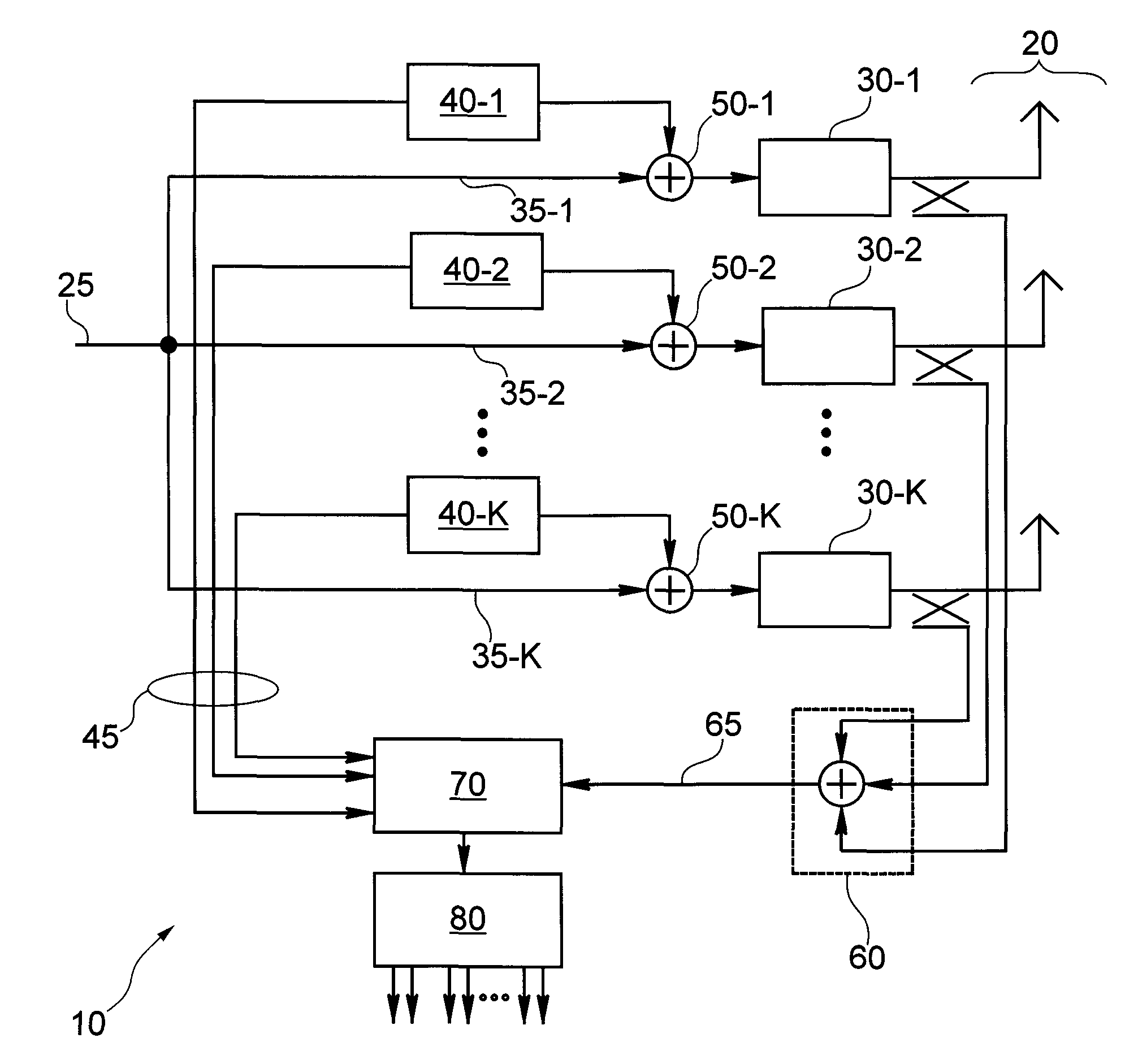
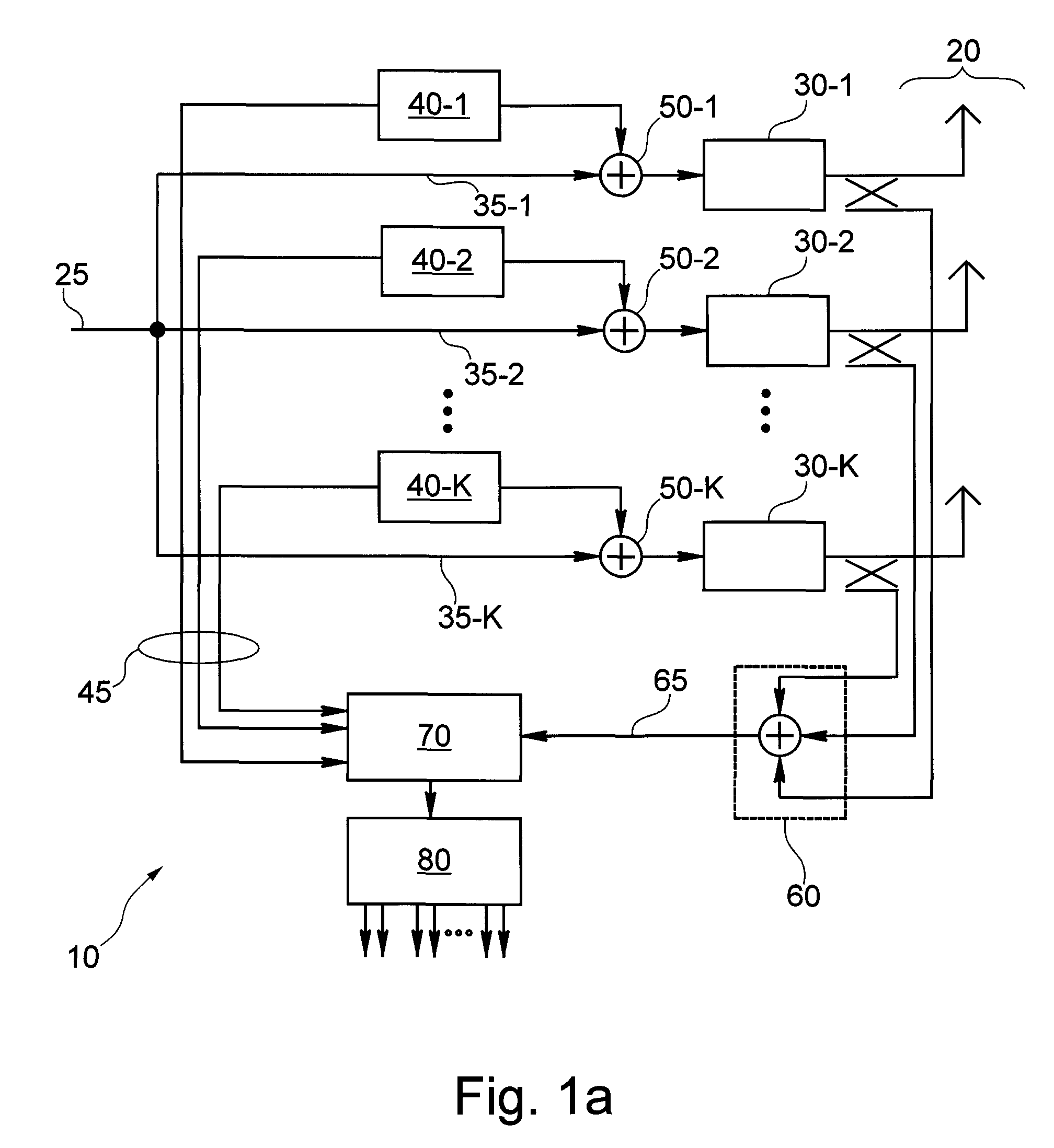
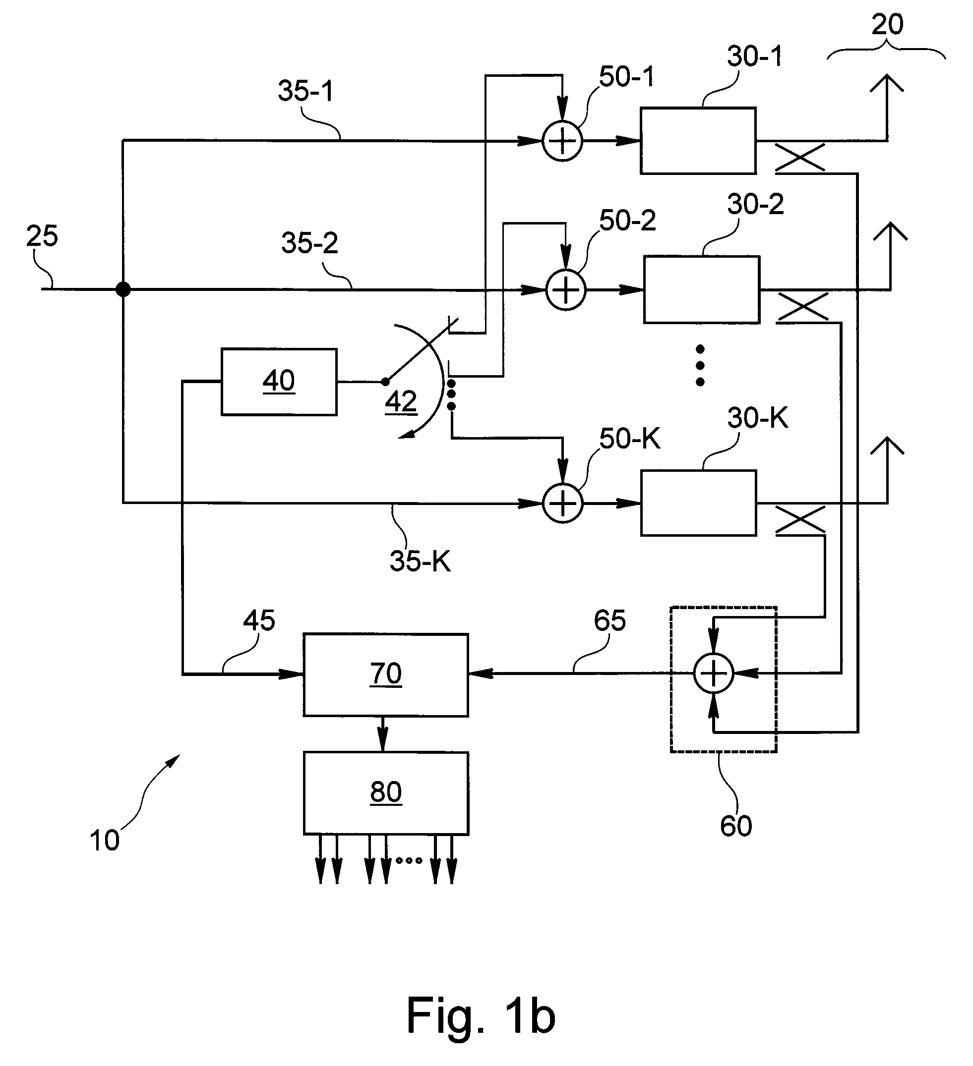
[0031]An object of the present system is to enhance a “classical” approach for pilot based online calibration in such a way that interference of a wanted payload signal to the i...


PUM


Abstract

An antenna array (10) for the transmission of signals (20) is disclosed. The antenna array (10) comprises: a plurality of transmission paths (30-1, 30-2, 30-K) for transmitting a plurality of wanted signals (25) and at least one calibration signal generator (40-1, 40-2,40-K) for the generation of at least one calibration signal (45). A plurality of calibration signal mixers (50-1, 50-2, 50-K) mixes the at least one calibration signal (45) with the plurality of wanted signals (25) to produce a plurality of transmission signals (20). A path sum signal device (60) sum the plurality of transmission signals (20) to produce a summed transmission signal (65); and an interference estimator (90) accepts the at least one calibration signal (45) and generates an estimated interference signal (92). An estimation signal mixer (95) subtracts from the summed transmission signal (65) the estimated interference signal (92) to produce a difference signal (97); and a on signal detection unit (70) for comparing the signal (97) with the at least one calibration signal (45).

Description

CROSS-REFERENCE TO RELATED APPLICATIONS[0001]This application claims the priority of and benefit to U.S. Provisional Application No. 61 / 074,372 filed on 20 Jun. 2008 and UK Patent Application No. 0811336.7 filed on 20 Jun. 2008. The entire disclosures of both applications are herein incorporated by reference.SUMMARY OF THE INVENTION[0002]The field of the invention relates to a method of calibration of an antenna array and an antenna array using the method of calibration.BACKGROUND OF THE INVENTION[0003]Active antenna arrays comprise a plurality of transceiver modules for receiving and transmitting signals. To operate the active antenna array in an efficient manner, transmitter paths to the transceiver modules have to be calibrated in order so that the transmitter paths work together in a coherent manner. In other words, magnitude and phase of individual signals on the transmitter paths have to be synchronized to ensure that the individual signals on the transmitter paths are coheren...

Claims


Application Information

Patent Timeline
Patent Type & Authority Applications(United States)
IPC IPC(8): H01Q3/00
CPCH01Q3/267
Inventor SCHLEE, JOHANNESWECKERLE, MARTINSCHMIDT, GEORGRIEGLER, MAIK
Owner TELEFON AB LM ERICSSON (PUBL)
Why Eureka
Try Eureka