
High productivity core drilling system

a drilling system and high-efficiency technology, applied can solve the problems of slow tripping of the core sample tube in the drill string, time-consuming and costly process for retrieving a core sample, and inability to achieve high efficiency, high productivity, and high efficiency in the field of drilling

Active Publication Date: 2010-01-21
LONGYEAR TM
View PDF64 Cites 40 Cited by
  • Summary
  • Abstract
  • Description
  • Claims
  • Application Information

AI Technical Summary

Benefits of technology

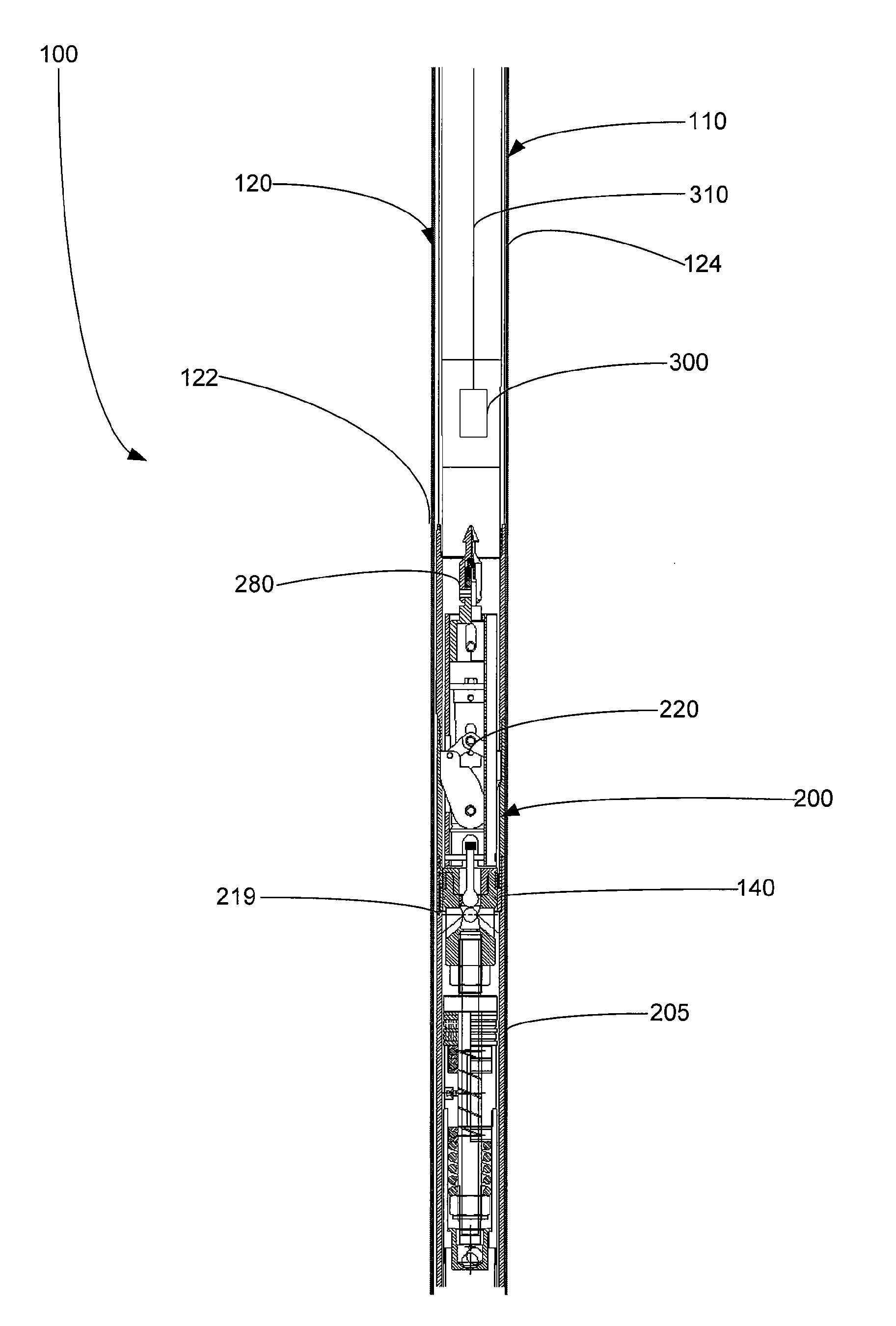
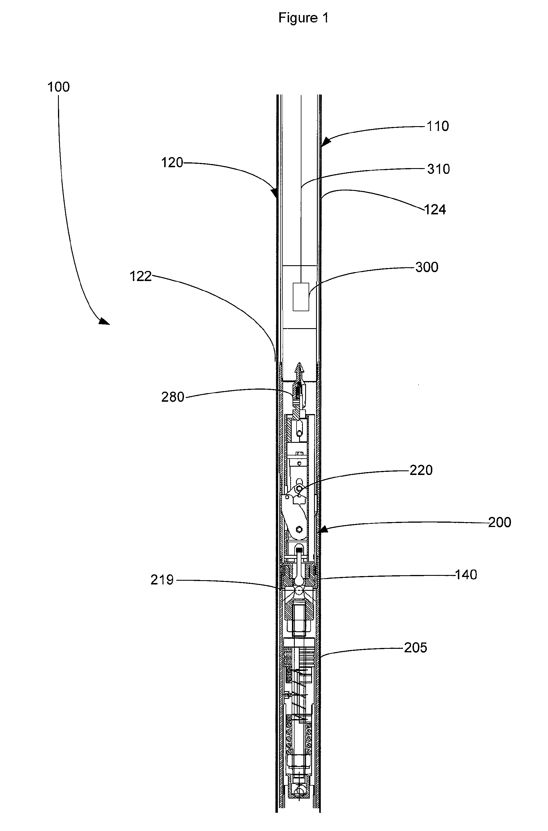
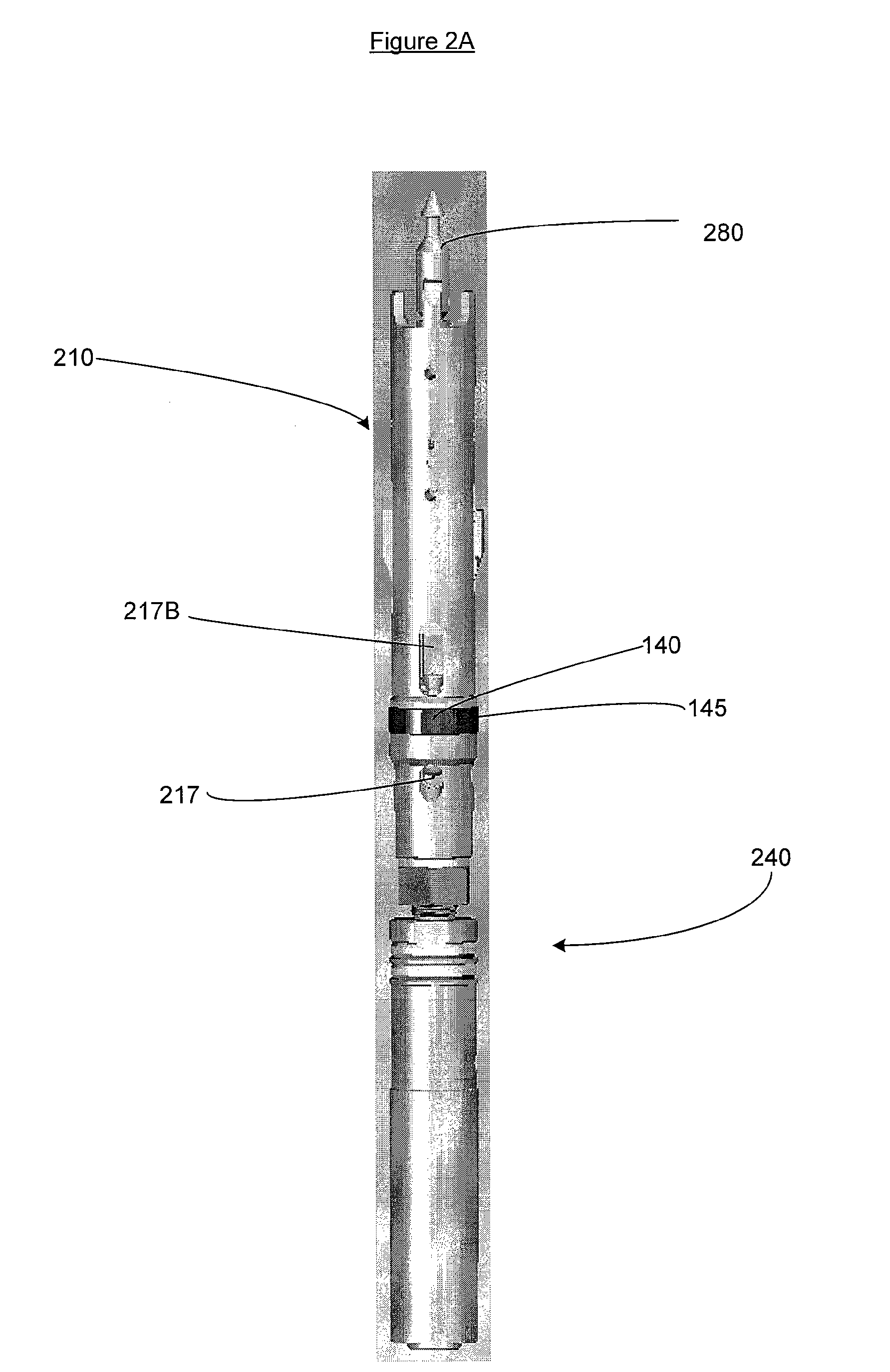
[0005]This application describes a high productivity core drilling system. The system includes a drill string, an inner core barrel assembly, an outer core barrel assembly, and a retrieval tool that connects the inner core barrel assembly to a wireline cable and hoist. The drill string comprises multiple variable geometry drill rods. The inner core barrel assembly comprises a latching mechanism that can be configured to not drag against the interior surface of the drill string during tripping. In some instances, the latching mechanism may be fluid-driven and contain a detent mechanism that retains the latches in either an engaged or a retracted position. The inner core barrel assembly also comprises high efficiency fluid porting. Accordingly, the drilling system significantly increases productivity and efficiency in core drilling operations by reducing the time required for the inner core barrel assembly to travel through the drill string.

Problems solved by technology

In such cases, retrieving a core sample may require the time consuming and costly process of removing the entire drill string (or tripping the drill string out) from the borehole.
While wireline systems may be more efficient than retracting and extending the entire drill string, the time to trip the core sample tube in and out of the drill string still often remains a time-consuming portion of the drilling process.
Often the latches of such a mechanism may drag against the interior surface of the drill string and, thereby, slow the tripping of the core sample tube in the drill string.
Additionally, because drilling fluid and / or ground fluid may be present inside the drill string, the movement of many conventional core retrieval assemblies within the drill string may create a hydraulic pressure that limits the rate at which the core sample tube may be tripped in and out of the borehole.

Method used


Image

  • High productivity core drilling system
  • High productivity core drilling system
  • High productivity core drilling system

Examples


Embodiment Construction

[0013]The following description supplies specific details in order to provide a thorough understanding. Nevertheless, the skilled artisan would understand that the drilling systems and associated methods can be implemented and used without employing these specific details. Indeed, the systems and associated methods can be placed into practice by modifying the systems and associated components and methods and can be used in conjunction with any existing apparatus, system, component, and / or technique conventionally used in the industry. For instance, while the drilling systems are described as being used in a downhole drilling operation, they can be modified to be used in an uphole drilling operation. Additionally, while the description below focuses on a drilling system used to trip a core barrel assembly into and out of a drill string, portions of the described system can be used with any suitable downhole or uphole tool, such as a core sample orientation measuring device, a hole di...


PUM


Abstract

High productivity core drilling systems are described. The system includes a drill string, an inner core barrel assembly, an outer core barrel assembly, and a retrieval tool that connects the inner core barrel assembly to a wireline cable and hoist. The drill string comprises multiple variable geometry drill rods. The inner core barrel assembly comprises a non-dragging latching mechanism, such as a fluid-driven latching mechanism that contains a detent mechanism that retains the latches in either an engaged or a retracted position. The inner core barrel assembly also comprised high efficiency fluid porting. Accordingly, the drilling system significantly increases productivity and efficiency in core drilling operations by reducing the time required for the inner core barrel assembly to travel through the drill string. Other embodiments are also described.

Description

1. FIELD OF INVENTION[0001]This application generally relates to the field of drilling. In particular, this application discusses a drilling system for drilling core samples that can increase drilling productivity by reducing the amount of time needed to place and retrieve a core sample tube (or sample tube) in a drill string.2. BACKGROUND AND RELATED ART[0002]Drilling core samples (or core sampling) allows observation of subterranean formations within the earth at various depths for many different purposes. For example, by drilling a core sample and testing the retrieved core, scientists can determine what materials, such as petroleum, precious metals, and other desirable materials, are present or are likely to be present at a desired depth. In some cases, core sampling can be used to give a geological timeline of materials and events. As such, core sampling may be used to determine the desirability of further exploration in a particular area.[0003]In order to properly explore an a...

Claims


Application Information

Patent Timeline
IPC IPC(8): E21B25/00E21B34/16E21B49/00E21B31/00
CPCE21B25/02
Inventor DRENTH, CHRIS LLOYD
Owner LONGYEAR TM
Learn More