
Solar power generation stabilization system and method

Active Publication Date: 2010-01-14
GENERAL ELECTRIC CO
View PDF6 Cites 83 Cited by
  • Summary
  • Abstract
  • Description
  • Claims
  • Application Information

AI Technical Summary

Benefits of technology

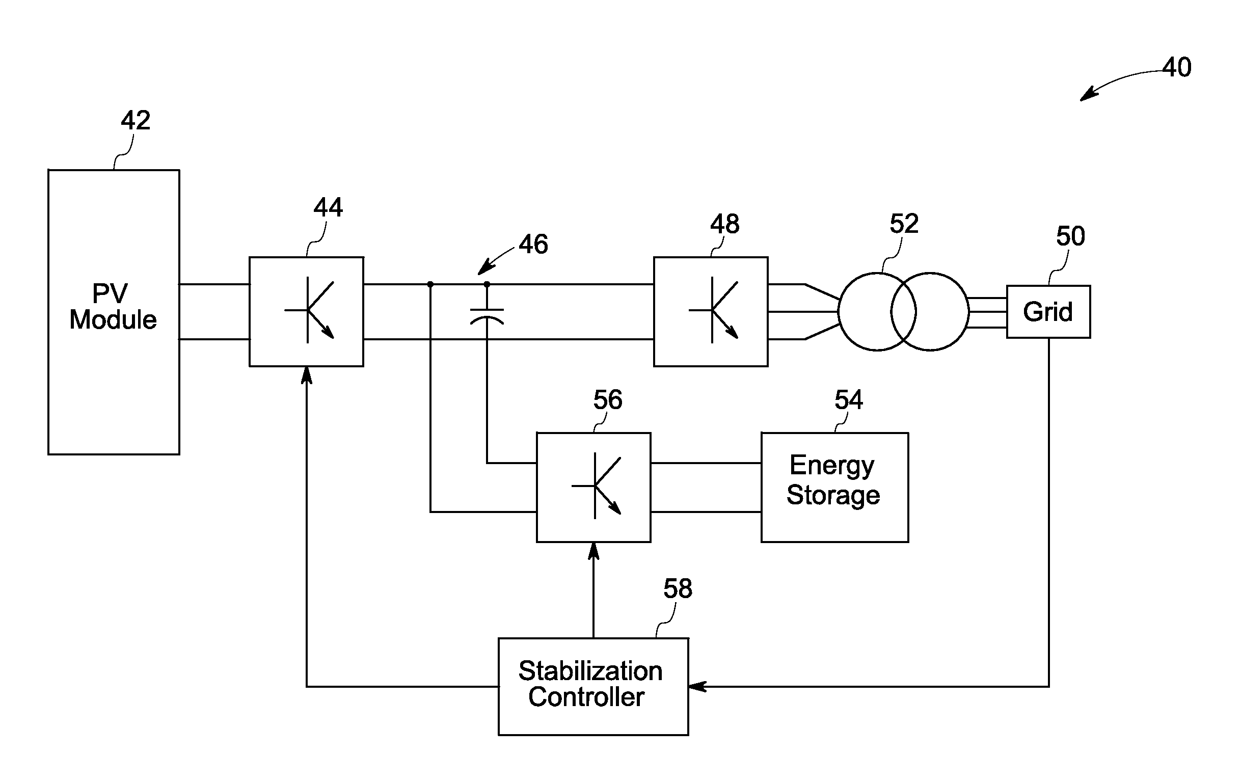
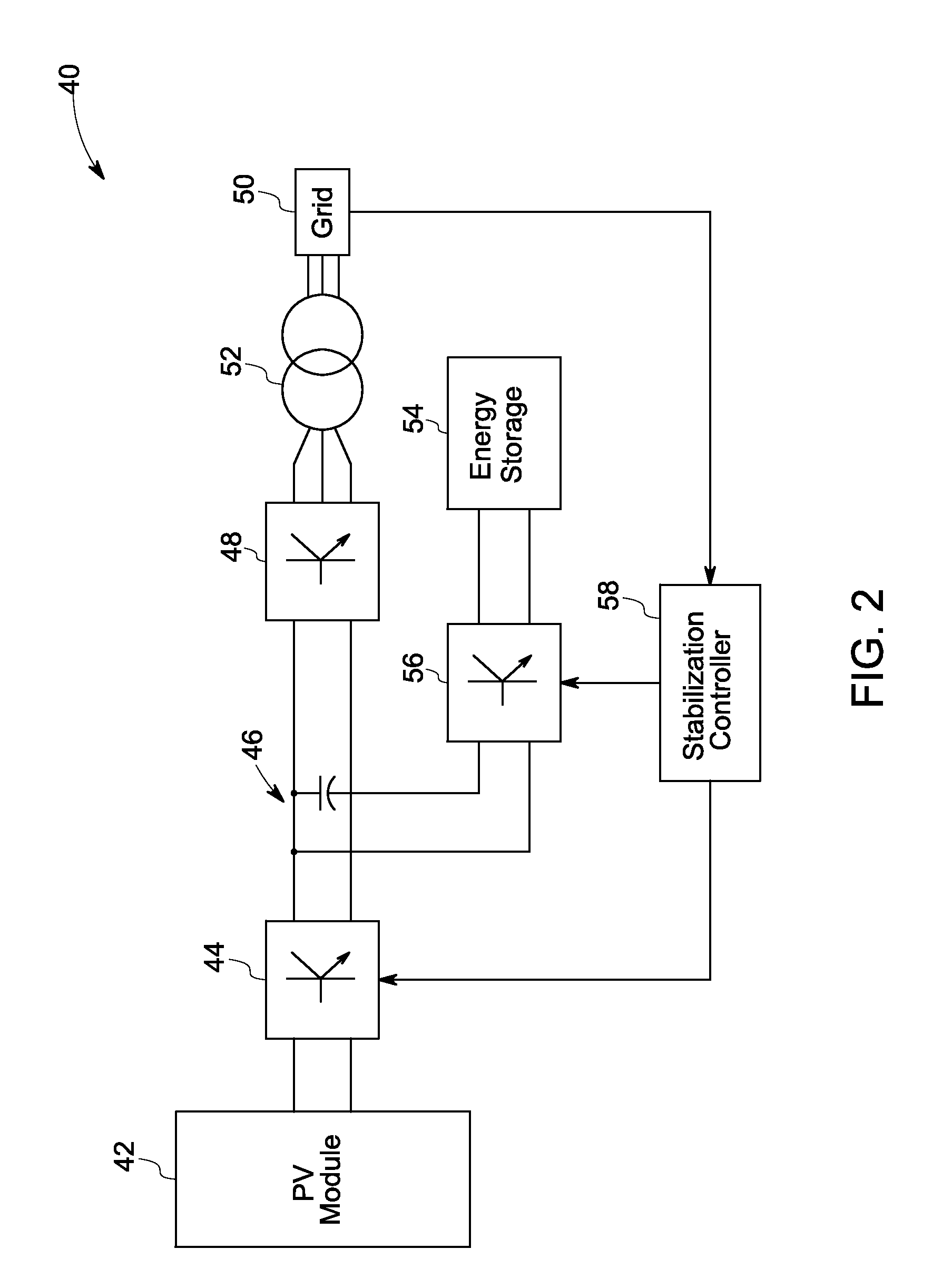
[0007]In accordance with an exemplary embodiment of the present invention, a power generation system is provided. The system comprises a DC to DC converter and a DC to AC converter coupled to the DC to DC converter. The combination of the DC to DC converter and the DC to AC converter is configured for supplying power from a photovoltaic module to a power grid. The system further includes a bidirectional converter coupled to the DC to AC inverter. The system also includes an energy storage device coupled to the bidirectional converte

Problems solved by technology

As new grid codes are developed for solar power generation systems, and as market penetration level o

Method used


Image

  • Solar power generation stabilization system and method
  • Solar power generation stabilization system and method
  • Solar power generation stabilization system and method

Examples


Embodiment Construction

[0016]As discussed in detail below, embodiments of the present invention function to provide a system and a method for transferring power from a solar power generation system to a power grid for stabilizing the grid frequency.

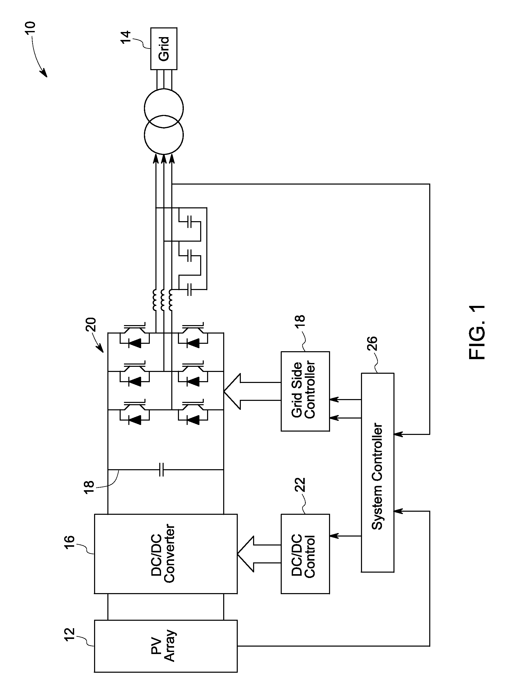
[0017]FIG. 1 illustrates a conventional solar power generation system 10. The power generation system includes a PV array 12 including a plurality of connected PV modules or PV strings (not shown). The PV array is connected to a power grid 14 through a DC / DC converter 16, a DC link 18, and a grid side three-phase DC / AC converter 20. The DC / DC converter 16 maintains a constant DC voltage at the DC link 18, and thus the energy flow from the PV module 12 to the power grid 14 is managed. The DC / DC converter 16 is controlled by a DC / DC controller 22, and the grid side converter 20 is controlled by a grid side controller 24. A system controller 26 generates a reference DC voltage command, a reference output voltage magnitude command, and a reference frequency command...


PUM


Abstract

A power generation system including a photovoltaic (PV) module to generate DC power is provided. The system includes a combination of a DC to DC converter and a DC to AC converter coupled to the DC to DC converter for supplying power from the PV module to a power grid. The system further includes a bidirectional converter and an energy storage device coupled to the bidirectional converter. The system also includes a control system to generate commands for controlling a state of charge of the energy storage device. The control system comprises a deadband limiter to detect a deviation of the frequency signal outside of a respective signal range, a power shaper to provide a transient power generation adjustment signal in response to the signal being outside of the respective signal range and a limit controller for preventing the adjustment signal from causing the energy storage device to operate outside of at least one operating constraint.

Description

CROSS REFERENCE TO RELATED APPLICATIONS[0001]This Application is a continuation-in-part of U.S. patent application Ser. No. 12 / 023,368, filed Jan. 31, 2008, which application is herein incorporated by reference.BACKGROUND[0002]The invention relates generally to a solar power generation system and more specifically to the use of energy storage in conjunction with a solar power generation system. The invention additionally relates to grid frequency stabilization of a grid connected solar power generation system.[0003]Solar power generation systems have photovoltaic (PV) modules, which produce electrical power. In order to feed the electrical power to the grid, power electronic elements are used for power conditioning. In one example, the power electronic elements include a direct current (DC) to DC converter and a DC to alternating current (AC) inverter connected back to back through a DC link.[0004]As new grid codes are developed for solar power generation systems, and as market pene...

Claims


Application Information

Patent Timeline
IPC IPC(8): H02M7/5387
CPCH01L31/02021H02J3/383Y02E10/566H02M7/48Y02E10/563H02J7/35H02J2300/24H02J3/381Y02E10/56
Inventor O'BRIEN, KATHLEEN ANNDELMERICO, ROBERT WILLIAM
Owner GENERAL ELECTRIC CO
Learn More