Mechanical flow battery
a flow battery and flow tube technology, applied in the direction of positive displacement liquid engine, piston pump, dynamo-electric machine, etc., can solve the problem of limiting the placement of the flywheel system on the moving platform
- Summary
- Abstract
- Description
- Claims
- Application Information
AI Technical Summary
Benefits of technology
Problems solved by technology
Method used
Image
Examples
Embodiment Construction
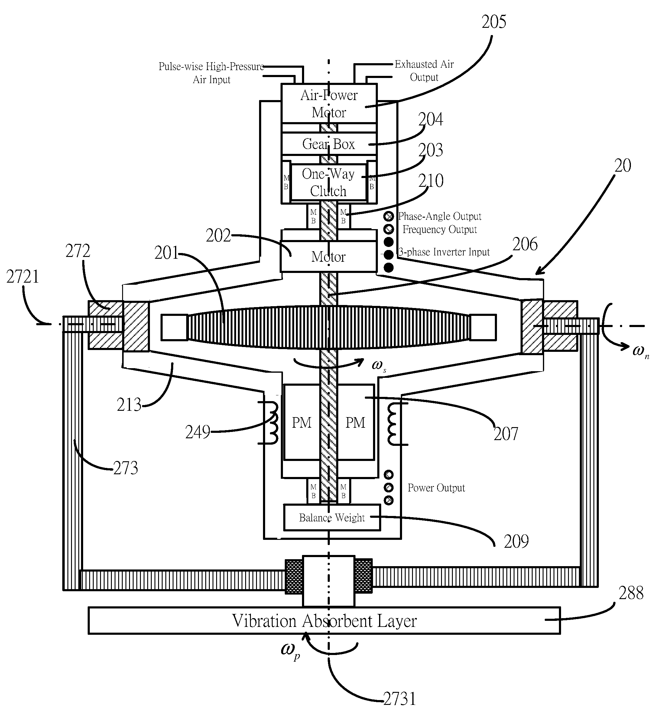
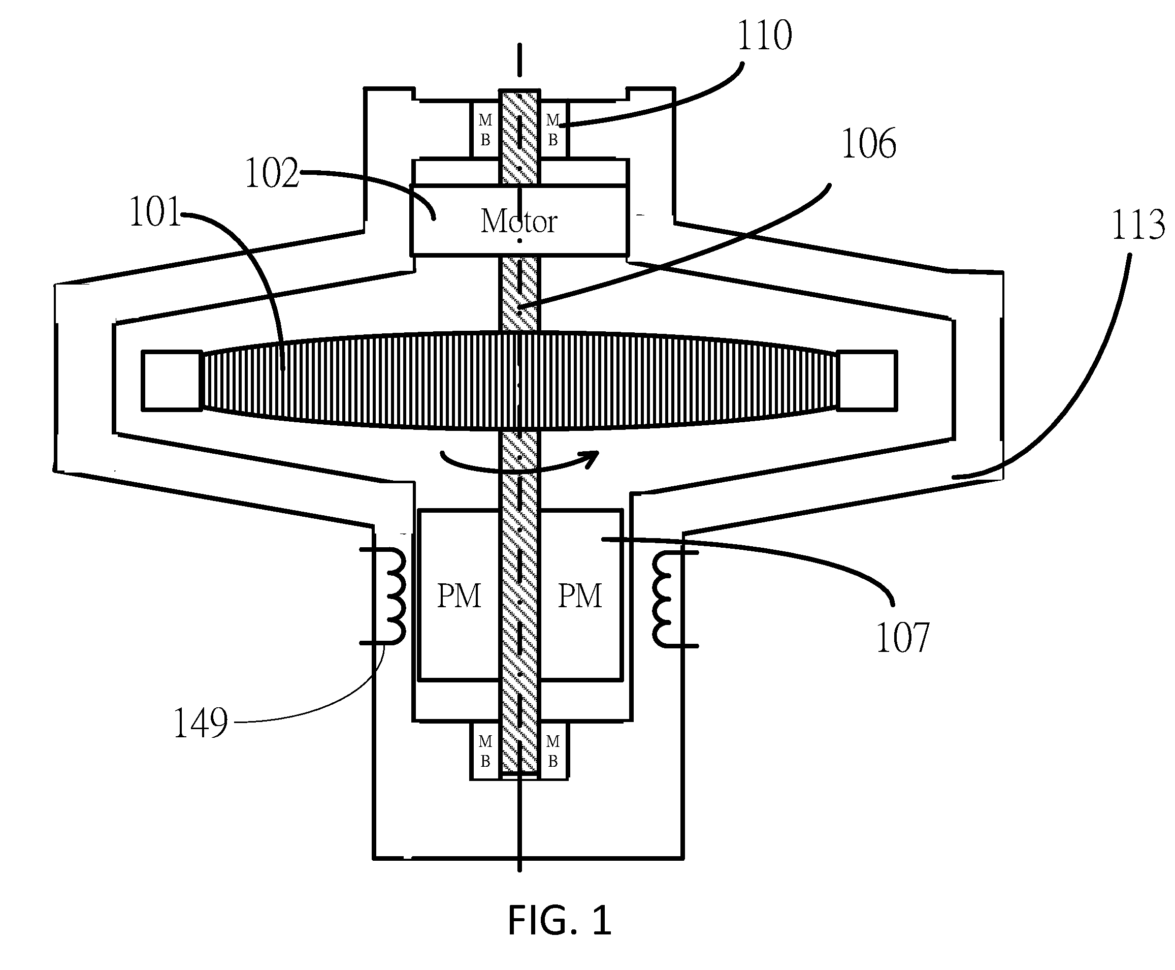
[0009]The present invention “a mechanical flow battery” can be fixed on a moving platform as a power generator and battery. The mechanical flow battery comprises a flywheel system in which a high-speed rotating rotor is sensitive to angular momentum so that it has to be isolated from any outside gyroscopic torque. The invention has employed the structure of gyroscope to solve the problems.
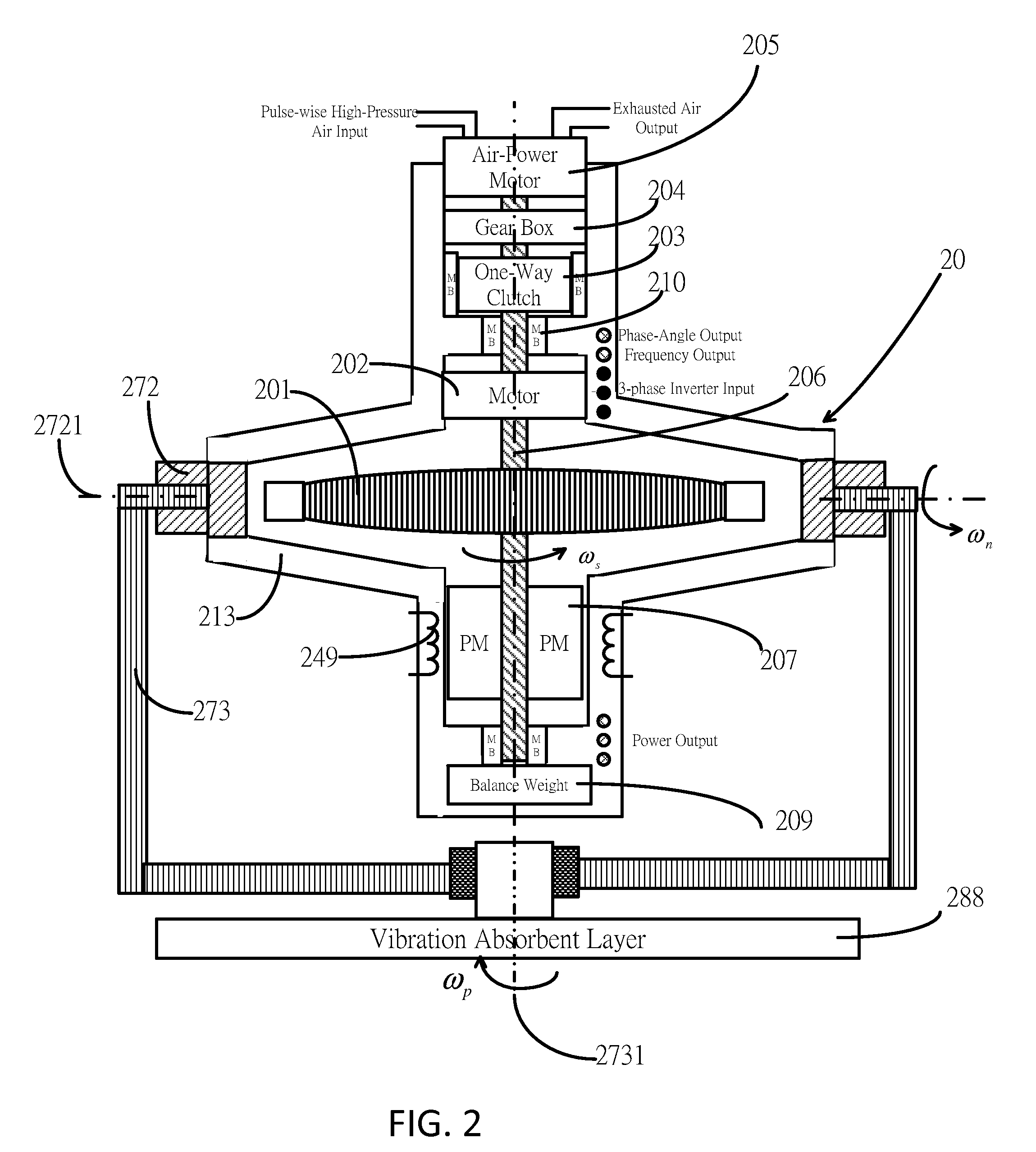
[0010]FIG. 2 has shown the present invention “a mechanical flow battery” or simply “flow battery” in cross view. The mechanical flow battery comprises a flywheel system 20, a nutation frame 272 and a precession frame 273 which is mounted on a vibration absorbent layer 288 to be isolated from any outside vibrations.
[0011]The flywheel system 20 of the mechanical flow battery comprises a rotor 201, a spinning axis 206, at least a permanent magnet shown by a number 207, a motor 202, a housing 213, at least a conductive coil shown by a number 249, a plurality of bearings shown by a number 210, an air-po...
PUM
 Abstract
Description
Claims
Application Information
 - R&D
- Intellectual Property
- Life Sciences
- Materials
- Tech Scout
- Unparalleled Data Quality
- Higher Quality Content
- 60% Fewer Hallucinations
Browse by: Latest US Patents, China's latest patents, Technical Efficacy Thesaurus, Application Domain, Technology Topic, Popular Technical Reports.
© 2025 PatSnap. All rights reserved.Legal|Privacy policy|Modern Slavery Act Transparency Statement|Sitemap|About US| Contact US: help@patsnap.com


