
Image processing apparatus, image processing method, program and recording medium

Inactive Publication Date: 2009-12-31
SONY CORP
View PDF7 Cites 117 Cited by
  • Summary
  • Abstract
  • Description
  • Claims
  • Application Information

AI Technical Summary

Benefits of technology

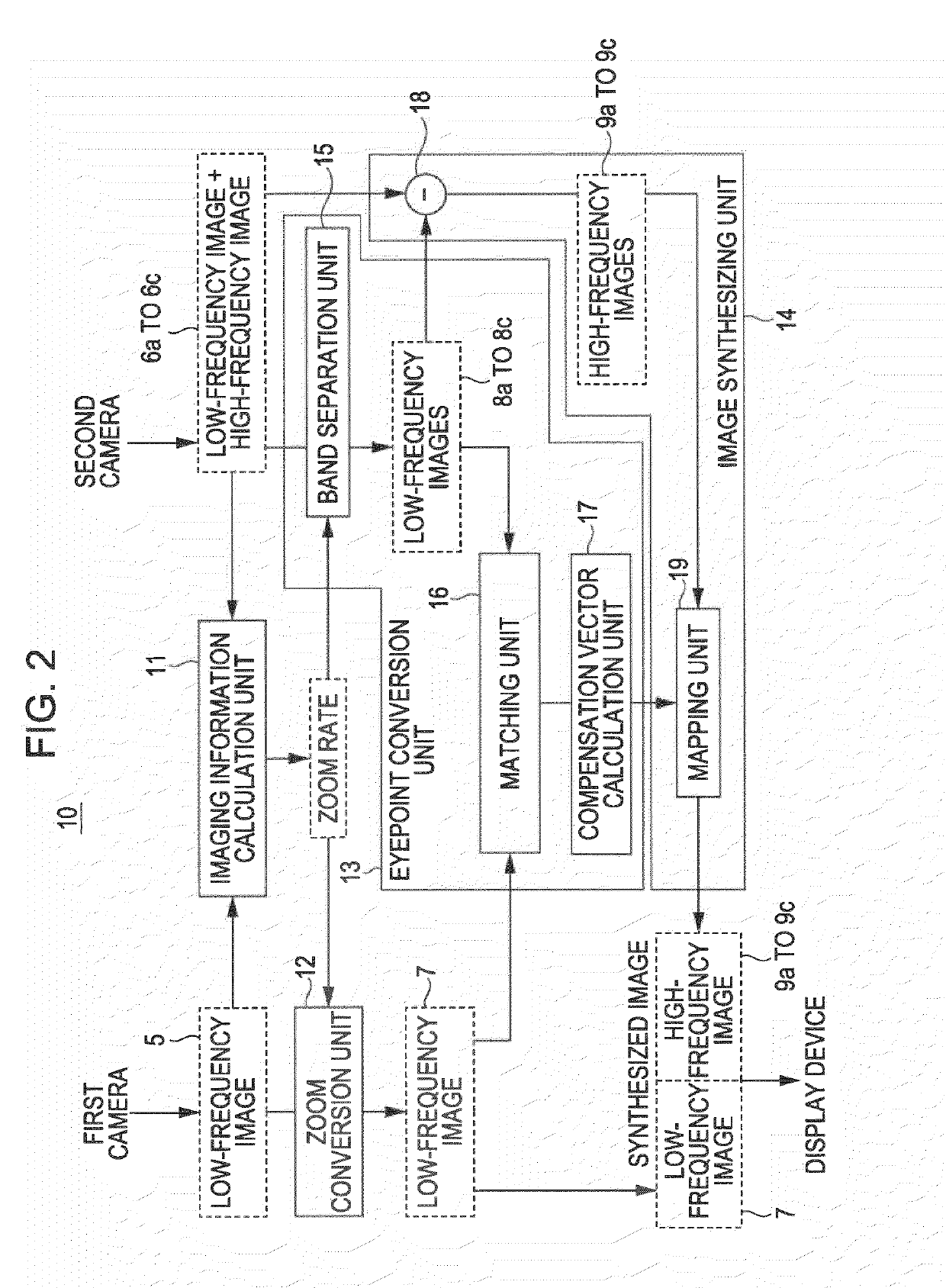
[0025]According to an embodiment of the invention, a first image generated by a first camera that captures a predetermined range at a first angle of view is acquired, a plurality of second images generated by a plurality of second cameras, each of which captures a portion of the predetermined range at a second angle of view that is narrower than the first angle of view are acquired, the second images being higher in resolution than the first image, and coordinate positions of the plurality of second images with respect to the first image and differences of imaging directions of the plurality of second cameras with respect to an imaging direction of the first camera are calculated as capturing information. Eyepoint conversion images that are obtained by converting the plurality of second images are generated on the basis of the differences of the imaging directions so that eyepoints of the plurality of second cameras are made to coincide with an eyepoint of the first camera, and the first image is matched with the eyepoint conversion images to calculate deviations in phase of the eyepoint conversion images with respect to the first image High-frequency images, formed of frequency components higher than or equal to a predetermined frequency band, are extracted from the plurality of second images, and the high-frequency images are pasted at the coordinate positions in correspondence with the first image so as to eliminate the deviations in phase of the eyepoint conversion images with respect to the first image to generate a synthesized image.
[0026]With the above configuration, it is possible to obtain a high-resolution synthesized image in a wide range without an unnatural peripheral portion of each image.
[0027]According to the embodiment of the invention, it is possible to obtain a high-resolution synthesized image in a wide range without an unnatural peripheral portion of each image, so it is advantageous in that, even when the synthesized image is displayed on a large screen, a joint between the images is smooth.

Problems solved by technology

However, when a plurality of objects are present within a capturing range of the cameras or when a plurality of cameras are arranged one above the other or side by side, it is difficult to piece the images smoothly.
However, even with the DRC, the band of an obtained high-resolution image is limited, so, for example, defects are conspicuous in each pixel when the image is enlarged.
In this technique, because assignment of a camera that captures a high-resolution image and a camera that calculates motion information is fixed, it is not easy to increase resolution.
For this reason, it is difficult to increase the resolution of an image with respect to the resolution of a solid-state image sensing device (for example, CMOS: Complementary Metal Oxide Semiconductor, CCD: Charge Coupled Device) provided for the camera that captures a static image.
In addition, in the technique described in Japanese Unexamined Patent Application Publication No. 9-139878, the respective lenses take charge of the foci of the long-distance view and the short-distance view to perform imaging; however, there is no focus common to a large number of cameras.
Thus, each camera easily becomes out-of-focus, so a pieced image tends to appear to be unnatural.

Method used


Image

  • Image processing apparatus, image processing method, program and recording medium
  • Image processing apparatus, image processing method, program and recording medium
  • Image processing apparatus, image processing method, program and recording medium

Examples


Embodiment Construction

[0057]Hereinafter, an embodiment of the invention will be described with reference to FIG. 1 to FIG. 25. In the present embodiment, an example in which an image processing apparatus 10 according to the embodiment of the invention is applied to an image processing system 1 to generate a high-resolution synthesized image with a wide imaging area will be described.

Example of Configuration of Image Processing System 1

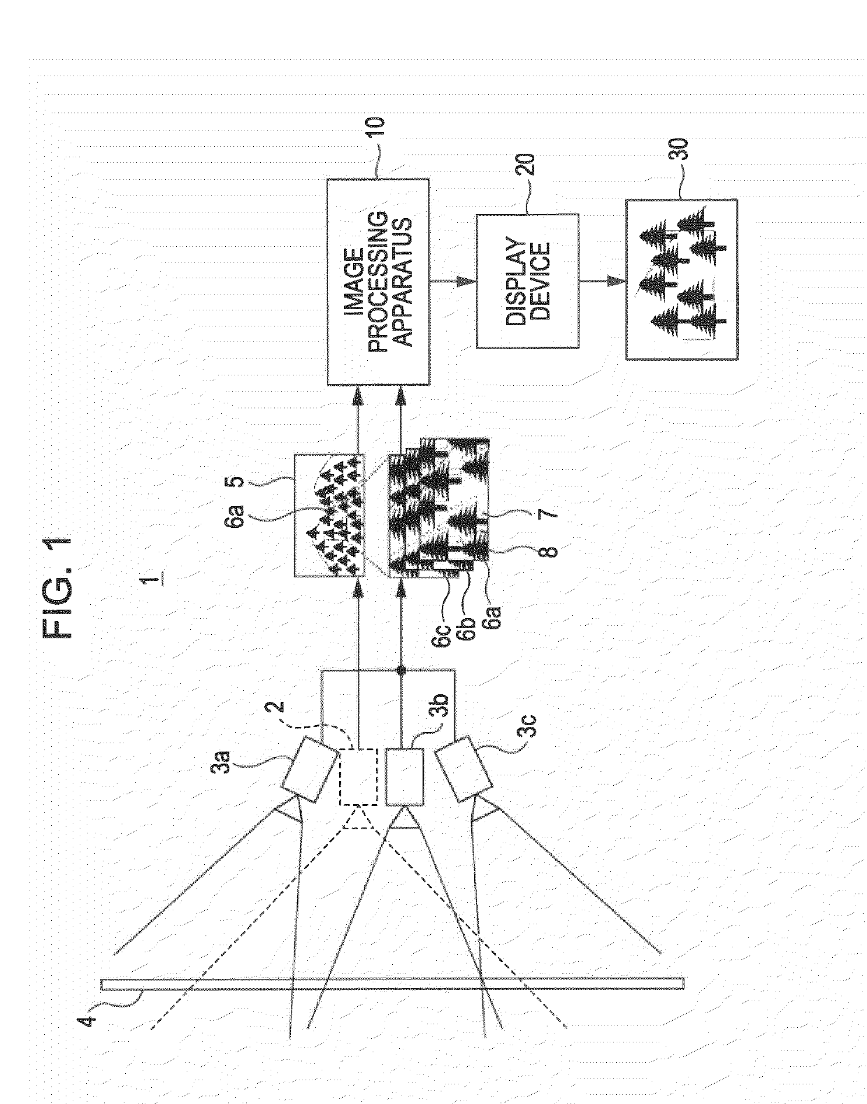
[0058]FIG. 1 shows an example of the configuration of the image processing system 1 according to the present embodiment. The image processing system 1 includes a first camera 2 and second cameras 3a to 3c. The first camera 2 captures a predetermined range at a first angle of view to generate a first image 5. The second cameras 3a to 3c capture portions of the predetermined range at second angles of view narrower than the first angle of view, and generate second images 6a to 6c. The first image 5 and the second images 6a to 6c are supplied to the image processing apparatus 1...


PUM


Abstract

An image processing apparatus includes: an imaging information calculation unit acquiring a first image and higher-resolution second images, and calculating coordinate positions of the second images to the first image and differences in imaging direction between second cameras and a first camera; an eyepoint conversion unit generating eyepoint conversion images obtained by converting the second images based on the differences in imaging direction so that eyepoints of the second cameras coincide with an eyepoint of the first camera and matching the first image with the eyepoint conversion images to calculate phase deviations of the eyepoint conversion images from the first image; and an image synthesizing unit extracting high-frequency images, having frequency components higher than or equal to a predetermined frequency band, from the second images, and pasting the high-frequency images at the coordinate positions in correspondence with the first image to eliminate the phase deviations to generate a synthesized image.

Description

BACKGROUND OF THE INVENTION[0001]1. Field of the Invention[0002]The invention relates to an image processing apparatus, image processing method, program and recording medium that are suitably applied, for example, when an image captured in a wide angle of view is projected onto a screen.[0003]2. Description of the Related Art[0004]In an existing art, in order to capture a landscape, or the like, in a wide angle of view, for example, a panoramic imaging method, a multi-camera imaging method in which a plurality of cameras are placed at a plurality of locations, an imaging method in which a low-resolution dynamic image is synthesized with a high-resolution static image, a multi-focus imaging method that uses a camera having a plurality of foci, and the like, are employed. Hereinafter, the above imaging methods will be simply described.[0005]In the panoramic imaging method, images captured by a plurality of cameras are pieced together to generate a wide-area image. The panoramic imagin...

Claims


Application Information

Patent Timeline
IPC IPC(8): G06K9/36G06K9/32
CPCG06T3/4038H04N5/23238G06T3/4053H04N23/698H04N5/262H04N5/265
Inventor KONDO, TETSUJIROKOKUBO, TETSUSHITANAKA, KENJIMUKAI, HITOSHIHIBI, HIROFUMITANAKA, KAZUMASAMORISAKI, HIROYUKI
Owner SONY CORP
Learn More