
Systems and Methods for Color Data Compression

Active Publication Date: 2009-12-31
KONICA MINOLTA LAB U S A INC
View PDF12 Cites 12 Cited by
  • Summary
  • Abstract
  • Description
  • Claims
  • Application Information

AI Technical Summary

Benefits of technology

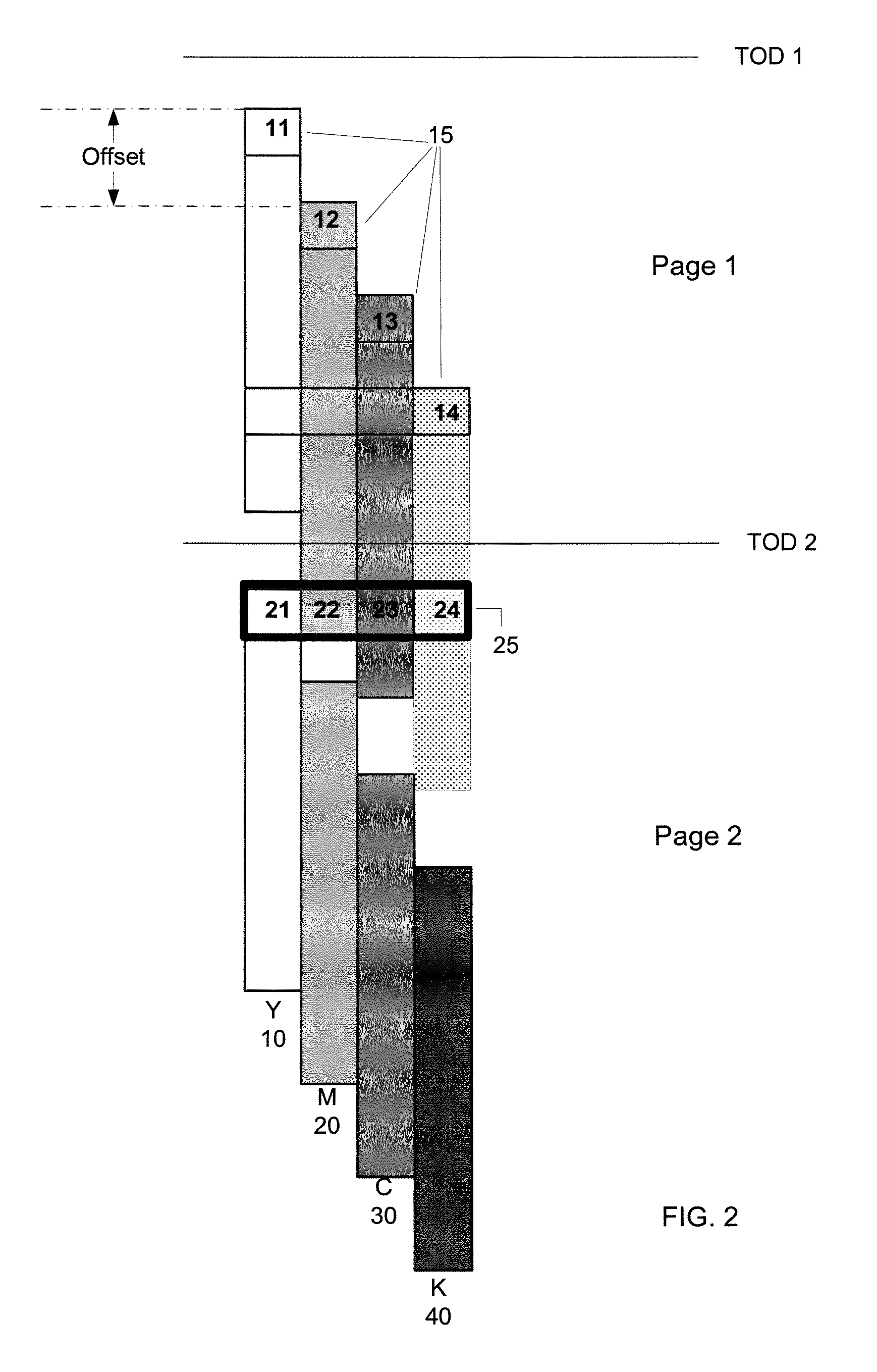
[0005]Systems and methods disclosed provide for reducing data size of at least one bitmap image, wherein the bitmap image comprises a plurality of color blocks, wherein each color block is associated with a distinct color plane. In some embodiments, the bitmap image may be compressed. At least one compressed color block that is contained in a transfer frame may be determined, based on information pertaining to a physical offset between successive color planes when they are rendered on a print medium. Further, at least one compressed color block in the transfer frame may be tagged, if the size of the transfer frame exceeds a threshold, and the resolution of the at least one compressed color block that is tagged may be reduced.

Problems solved by technology

Some printing systems, such as laser printing systems, may have hard real-time requirements so that once a print job has been initiated, data transfers to the print engine may occur at some set speed without interruption.
However, the bandwidth of the data transferring interface sometimes may not be sufficient to sustain the print speed.
When such a page is being transferred to the print controller from a printer at the print speed, the image data may exceed the bandwidth for some time period.
As a result, the page for printing may not be completely transmitted to the print controller and print engine before the start of physical printing, resulting in a data under-run.
Consequently, the page may not be printed properly.
The performance of the printing system may therefore be significantly compromised.
This may add substantial cost to the printing system.
In addition, memory cannot typically be added by users to many existing printers, so an approach using additional memory will not help printers already on the market.

Method used


Image

  • Systems and Methods for Color Data Compression
  • Systems and Methods for Color Data Compression
  • Systems and Methods for Color Data Compression

Examples


Embodiment Construction

[0014]Reference will now be made in detail to various embodiments, which are illustrated in the accompanying drawings. Wherever possible, the same reference numbers will be used throughout the drawings to refer to the same or like parts.

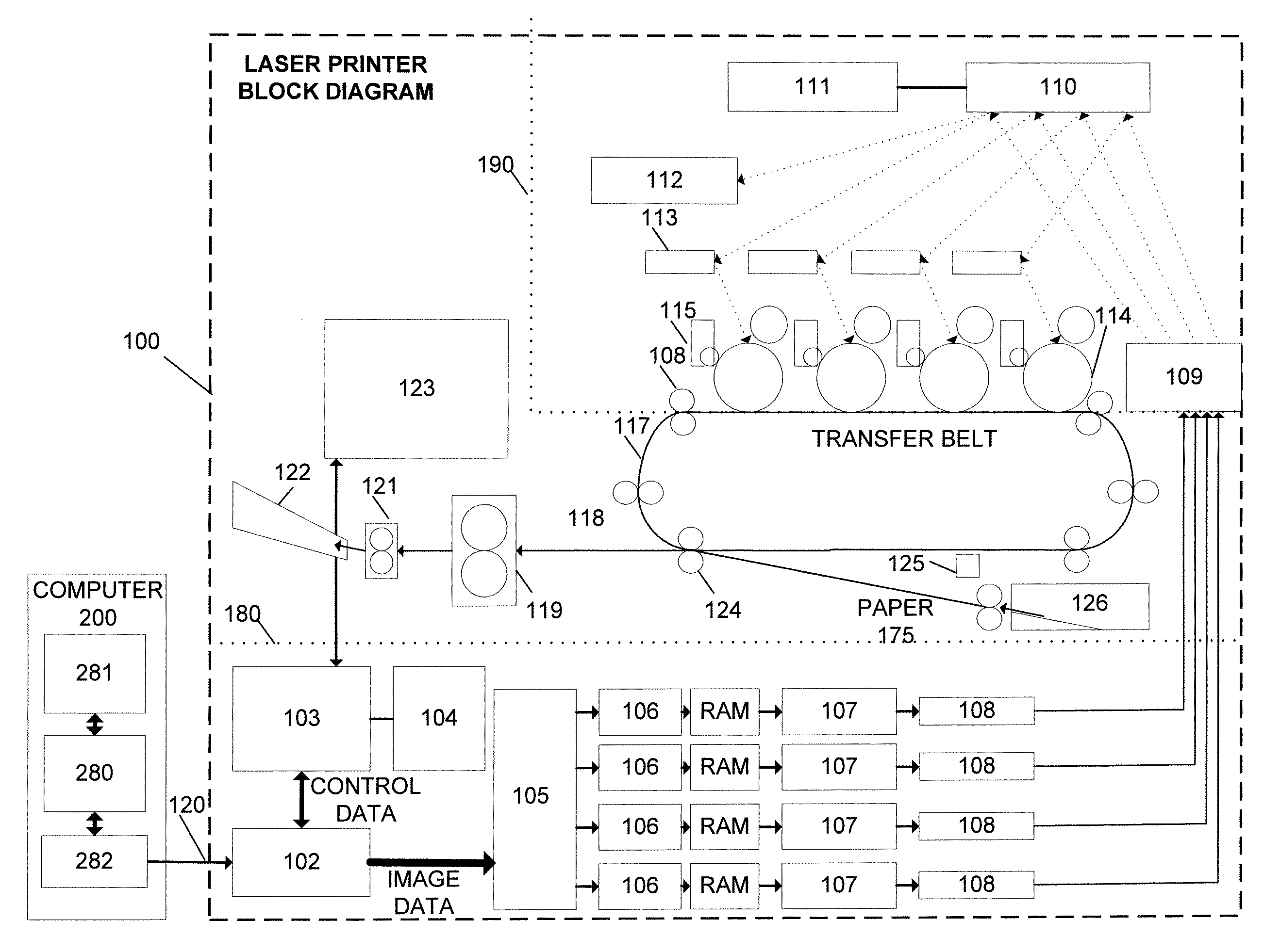
[0015]FIG. 1 is a block diagram of exemplary printer 100, which is coupled to exemplary computer 200. In some embodiments, printer 100 may be a laser printer, an LED printer, or any other printer consistent with principles of the present invention. Connection 120 couples computer 200 and printer 100 and may be implemented as a wired or wireless connection using conventional communication protocols and / or data port interfaces. In general, connection 120 can be any communication channel that allows transmission of data between the devices. In one embodiment, for example, the devices may be provided with conventional data ports, such as USB, FIREWIRE and / or serial or parallel ports for transmission of data through appropriate connection 120. The communi...


PUM


Abstract

Systems and methods are provided for reducing data size of at least one bitmap image, wherein the bitmap image comprises a plurality of color blocks, wherein each color block is associated with a distinct color plane. In some embodiments, the bitmap image may be compressed. At least one compressed color block that is contained in a transfer frame may be determined, based on information pertaining to a physical offset between successive color planes when they are rendered on a print medium. Further, at least one compressed color block in the transfer frame may be tagged, if the size of the transfer frame exceeds a threshold, and the resolution of the at least one compressed color block that is tagged may be reduced.

Description

TECHNICAL FIELD[0001]This disclosure relates to data compression for printing systems and in particular, to systems and methods for color data compression on laser printers.DESCRIPTION OF RELATED ART[0002]A typical printing system may include a print engine that controls various mechanical and electrical parts configured to print data on a page at a predetermined print speed. The print engine is usually controlled by a print controller, which communicates with a print data input device (e.g., a personal computer) and the print engine, to coordinate timing and other parameters related to the printing process. The print controller may receive image data for printing from the input device at an appropriate rate via a data transferring interface, can generate rasterized images, and send them to the print engine for printing.[0003]Some printing systems, such as laser printing systems, may have hard real-time requirements so that once a print job has been initiated, data transfers to the ...

Claims


Application Information

Patent Timeline
IPC IPC(8): G06K9/36
CPCH04N1/648
Inventor JOHNSTON, PETER
Owner KONICA MINOLTA LAB U S A INC
Learn More