
Image forming apparatus with display apparatus mounted

a technology of display apparatus and forming apparatus, which is applied in the direction of digital output to print units, instruments, static indicating devices, etc., can solve the problems of difficult to frequently change advertisements, difficult to perform detailed publicity activities, and often forgotten, so as to reduce the burden on the delivery person, increase the freedom of layout, and facilitate the maintenance of each apparatus

Active Publication Date: 2009-12-17
SHARP KK
View PDF8 Cites 3 Cited by
  • Summary
  • Abstract
  • Description
  • Claims
  • Application Information

AI Technical Summary

Benefits of technology

[0017]The present invention was made in order to address the problems described above, and it is an object thereof to provide an image forming apparatus on which a display apparatus is mounted, with which it is possible to obtain an adequate publicity effect to walkway pedestrians, without requiring a large installation location and with very simple installation work.
[0019]With this sort of configuration, the display apparatus and the image forming apparatus can be separated, so it is possible to reduce the burden on a delivery person when bringing in or moving the apparatus. Also, because it is possible for each apparatus to operate independently even when separated, it is possible to increase the freedom of the layout of the image forming apparatus and the display apparatus. Further, there is the advantage that by separating the display apparatus and the image forming apparatus, maintenance of each apparatus is easy to perform.
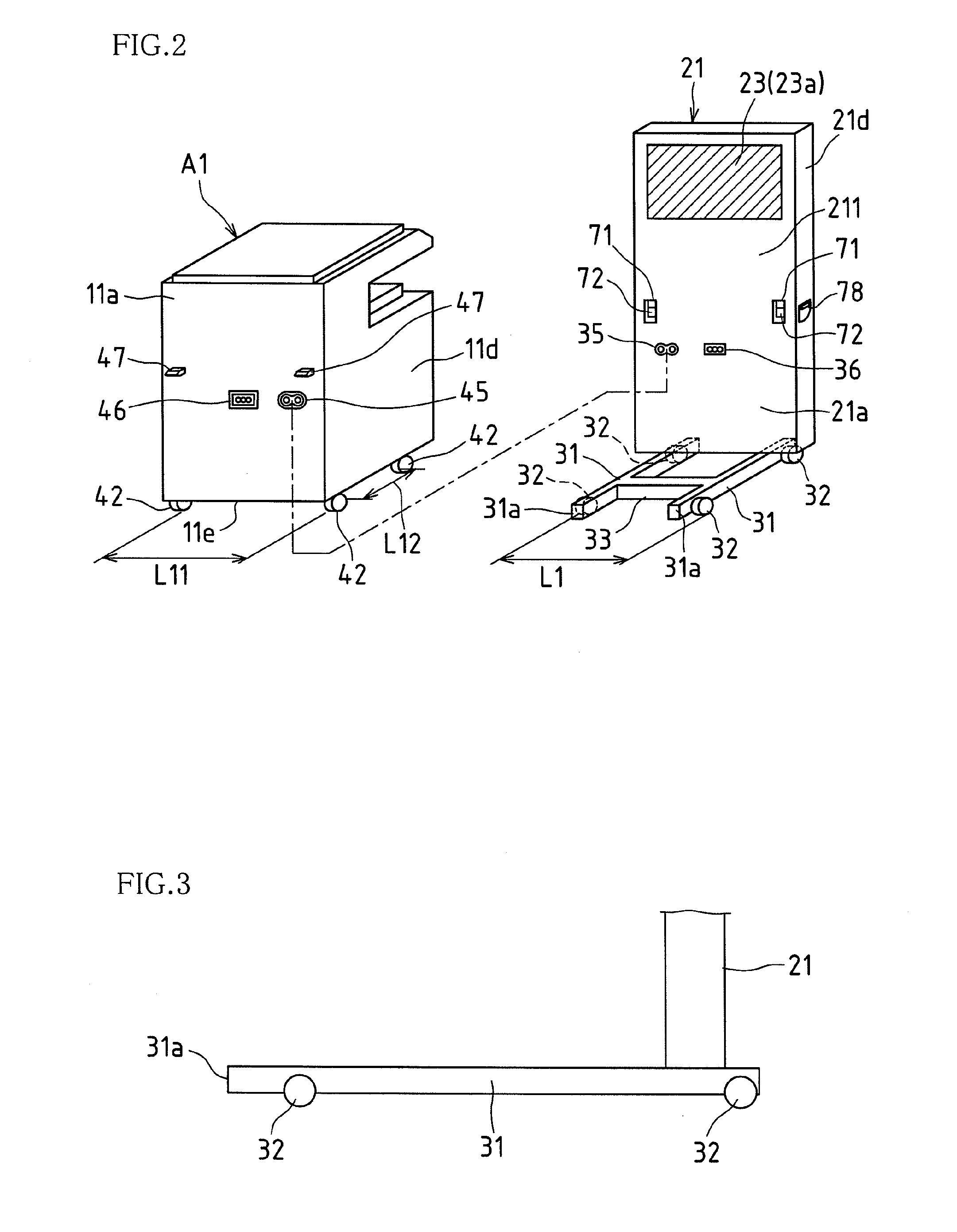
[0020]Also, in the present invention, the display apparatus is provided with a support leg, and in a state in which the display apparatus and the image forming apparatus have been connected, the support leg of the display apparatus is stored under the image forming apparatus. Thus, when the display apparatus and the image forming apparatus have been connected, the support leg of the display apparatus does not protrude from the image forming apparatus, so it is possible to suppress the installation area to a minimum.
[0022]Also, in the present invention, a configuration may be adopted in which a pair of support legs of the display apparatus are provided so as to have a predetermined space between the support legs, and in a state in which the display apparatus and the image forming apparatus have been connected, the support legs of the display apparatus are stored under the image forming apparatus. Thus, when the display apparatus and the image forming apparatus have been connected, the support legs of the display apparatus do not protrude from the image forming apparatus, so it is possible to suppress the installation area to a minimum.
[0024]Also, in the present invention, a configuration may be adopted in which a pair of support legs of the display apparatus are provided so as to have a predetermined space between the support legs, and in a state in which the display apparatus and the image forming apparatus have been connected, the image forming apparatus is stored between the support legs of the display apparatus. That is, when the display apparatus is disposed on the back face of the image forming apparatus, the space between the support legs of the display apparatus is no less than the lateral width of the image forming apparatus, and when the display apparatus is disposed on a side face of the image forming apparatus, the space between the support legs of the display apparatus is no less than the depth-wise width of the image forming apparatus. Thus, in a state in which the display apparatus and the image forming apparatus have been connected, the support legs of the display apparatus hold, in a sandwiching manner, the front and rear faces of the image forming apparatus, or the left and right faces of the image forming apparatus. Therefore, it is possible to stably dispose the display apparatus.
[0026]In this way, in the present invention, a configuration is adopted in which the display apparatus and the image forming apparatus can be separated, so it is possible to reduce the burden on a delivery person when bringing in or moving the apparatus. Also, because it is possible for each apparatus to operate independently even when separated, it is possible to increase the freedom of the layout of the image forming apparatus and the display apparatus. Further, there is the advantage that by separating the display apparatus and the image forming apparatus, maintenance of each apparatus is easy to perform.

Problems solved by technology

With this sort of publicity activity, it is difficult to frequently change advertisements, so there is the problem that detailed publicity activity cannot be performed depending on time spans, in which, for example, advertising targeted to businessmen is carried out during a time span in which many businessmen pass by, and advertising targeted to housewives or students is carried out during a time span in the daytime in which there are many housewives or students.
However, in this case as well, it is necessary for employees to manually remove information of real estate that is under a rental contract or purchase contract, and post new real estate information or the like, so there is the problem that removal, posting, or the like is frequently forgotten, and therefore the provided information may not be the newest information.
However, with the technology described in Patent Document 1, it is necessary to install a display along the entire walkway-side wall face, and connect this display to a printer installed within the store with a communications cable, so much installation work is needed, and installation in each store is necessary, so there is the problem that installation work is very complicated.
Also, there is the problem that after installation is performed once, it is not possible to easily change the layout according to circumstances.
Also, there is the problem that by only displaying advertising information on an operation screen of an image forming apparatus or a display screen of a cash register, even most customers inside the store do not notice the advertising information, and thus an adequate publicity effect is not obtained.
Also, in the technology described in Patent Document 3, there is the problem that an apparatus disconnected from a power supply unit cannot be used.
Additionally, the image forming apparatus and a large screen (for example, such as 50 inches) display apparatus connected by a cable are installed in stores, but in a store such as a convenience store or a supermarket, the question of how much selling area to secure is an issue, and because placement of two large devices in this manner results in a reduction in selling area, this approach has not been widely adopted.
Also, at present, it may not be possible to secure an installation location in a small store, and so the system is not necessarily advantageous to the store.

Method used


Image

  • Image forming apparatus with display apparatus mounted
  • Image forming apparatus with display apparatus mounted
  • Image forming apparatus with display apparatus mounted

Examples


Embodiment Construction

[0041]Hereinafter, embodiments of the present invention will be described with reference to the accompanying drawings.

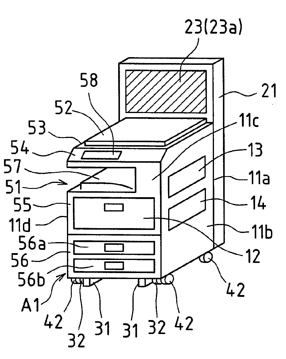
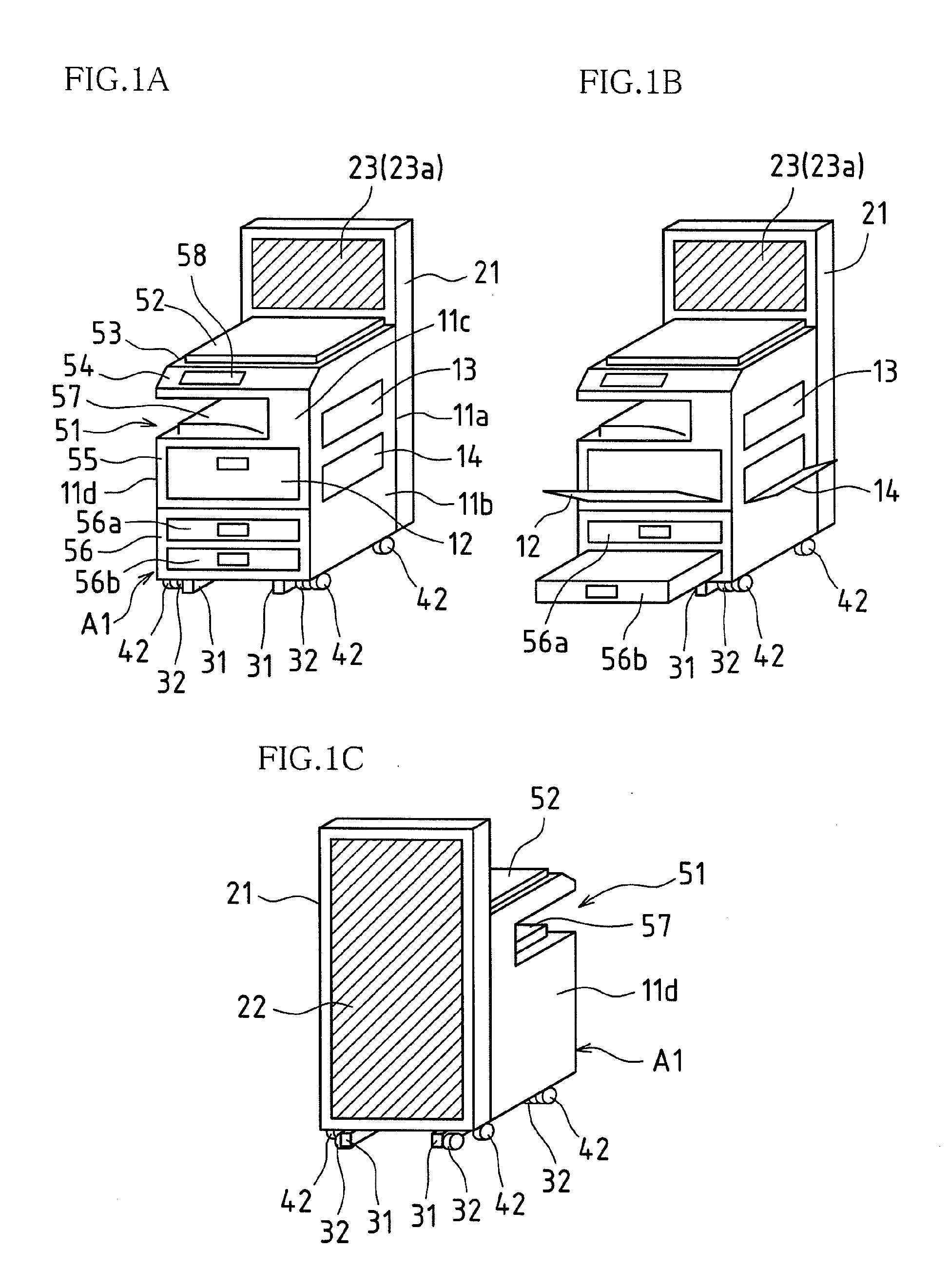
[0042]FIGS. 1A to 1C are outer perspective views of an image forming apparatus A1 on which a display apparatus is mounted, according to an example of the present invention.

[0043]The image forming apparatus A1 is an image forming apparatus with an in-body paper discharge structure formed in a sideways U shape when viewed from the front. In the image forming apparatus A1, an original pressing lid 52, an original reading portion 53, and a scanner portion 54 are disposed above an in-body paper discharge opening portion 51, and an image forming portion 55 and a paper supply portion 56 are disposed below the in-body paper discharge opening portion 51. Also, a keyboard-type and touch panel-type operation portion 58 is disposed on the front face of the original reading portion 53.

[0044]That is, the image forming apparatus A1 is surrounded by a back face case 11a and a right ...


PUM


Abstract

In an image forming apparatus serving as one embodiment, a large-format display that has a display screen visible from a rear face or a side face is disposed on at least one side face of a case of the image forming apparatus, and is formed such that the large-format display and the image forming apparatus are separable. The large-format display is provided with a pair of legs disposed so as to have a predetermined space L between the legs, and this space between the legs is formed so as to be no more than the lateral width of the image forming apparatus, and no more than the depth-wise width of the image forming apparatus.

Description

CROSS-REFERENCE TO RELATED APPLICATION[0001]This application claims priority under 35 U.S.C. §119(a) on Japanese Patent Application No. 2008-156924 filed in Japan on Jun. 16, 2008, the entire contents of which are herein incorporated by reference.TECHNICAL FIELD[0002]The present invention relates to an image forming apparatus such as a multifunction peripheral or digital copier, and more specifically relates to an image forming apparatus on which a display apparatus is mounted, in which a large-format display apparatus is integrated with the image forming apparatus.BACKGROUND ART[0003]Recently, image forming apparatuses such as multifunction peripherals and digital copiers are often installed in daily commodity stores or the like such as convenience stores and supermarkets, and such image forming apparatuses are mainly used, for example, when a user that uses the store takes a copy of an original.[0004]Incidentally, in recent convenience stores, the portion of the store that faces t...

Claims


Application Information

Patent Timeline
IPC IPC(8): H04N1/00
CPCH04N1/00129H04N1/00496H04N1/00493H04N1/00411
Inventor NAKAI, YASUHIROMACHINO, SATOSHIUEDA, OSAMU
Owner SHARP KK
Learn More