
Acceleration compensated inclinometer

a technology of accelerometer and inclinometer, which is applied in wave based measurement systems, instruments, navigation instruments, etc., can solve the problems of less accurate positioning of global navigation satellite systems and louder altitude and vertical heading angles

Active Publication Date: 2009-12-17
TRIMBLE NAVIGATION LTD
View PDF35 Cites 50 Cited by
  • Summary
  • Abstract
  • Description
  • Claims
  • Application Information

AI Technical Summary

Benefits of technology

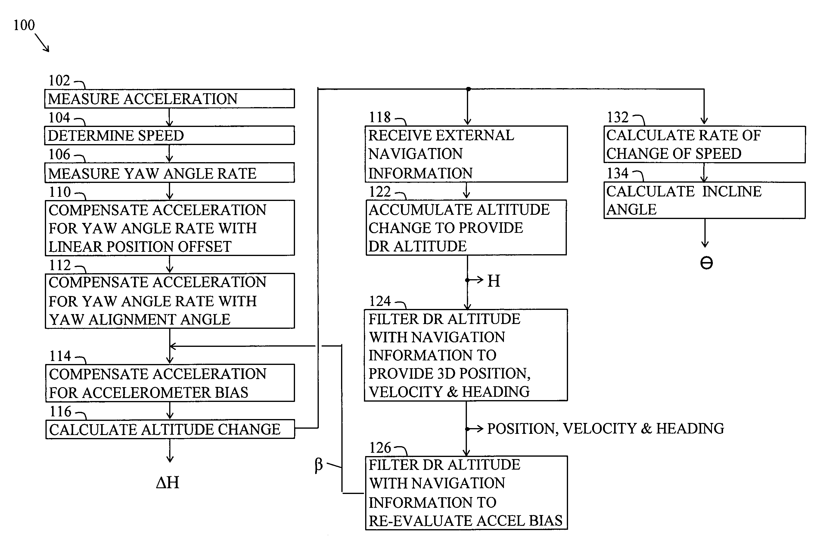
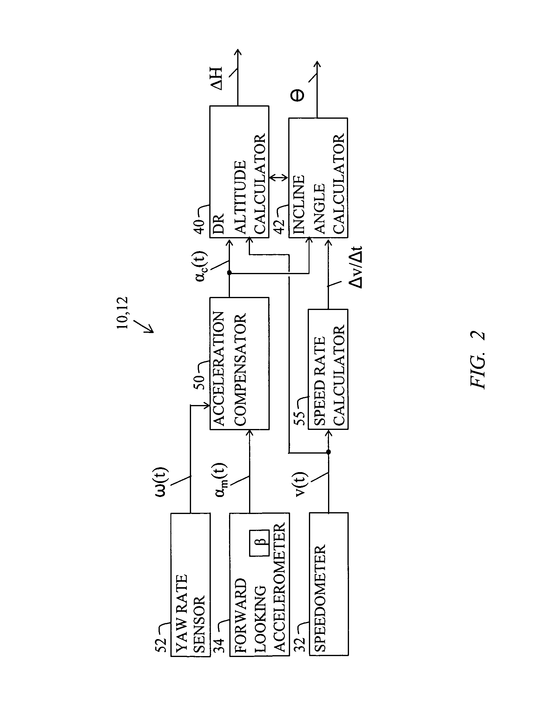
The present invention describes an apparatus and method for measuring changes in altitude and incline angle by measuring forward motion. The apparatus includes a speedometer, accelerometer, and DR calculator to calculate altitude change and incline angle based on the speed, acceleration, and yaw angle rate. The method involves measuring yaw angle rate and compensating the acceleration accordingly. The invention can be used in various applications such as sports equipment, vehicles, and navigation systems. The technical effects of the invention include improved accuracy and efficiency in measuring altitude and incline angle, which can enhance the performance and reliability of the equipment and systems.

Problems solved by technology

Further, global navigation satellite system positioning tends to be less accurate and noisier for altitude and vertical heading angles than for horizontal positions and horizontal heading angles.

Method used


Image

  • Acceleration compensated inclinometer
  • Acceleration compensated inclinometer
  • Acceleration compensated inclinometer

Examples


Embodiment Construction

[0036]The details of preferred embodiments and best mode for carrying out the ideas of the invention will now be presented. It should be understood that it is not necessary to employ all of the details of the preferred embodiments in order to carry out the idea of the invention.

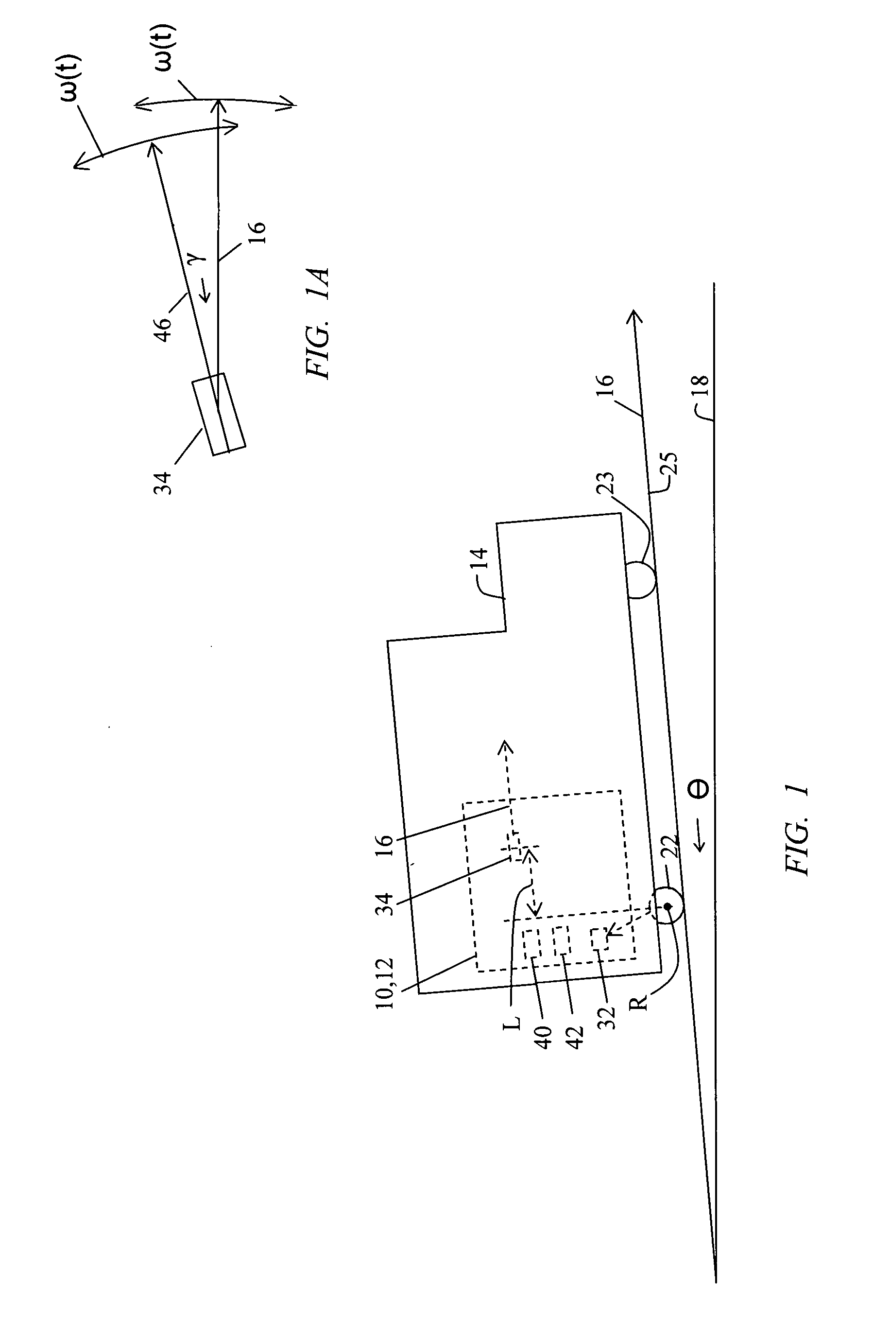
[0037]FIG. 1 shows a dead reckoning (DR) altimeter apparatus and an inclinometer apparatus referred to with reference numbers 10 and 12, respectively. The apparatus 10,12 is intended to be carried in a vehicle 14 where the vehicle 14 has a forward motion direction 16 having an unknown incline angle θ from the horizontal plane 18. The vehicle 14 can be an automobile, truck, train, trolley or the like having rear wheels 22 and front wheels 23 on the ground 25.

[0038]The apparatus 10,12 includes a speedometer 32 and a forward-looking linear accelerometer 34. The vehicle 14 has a turn radius line R (FIG. 5) perpendicular to the vehicle 14 through a turn center 92 (FIG. 5) of the vehicle 14. For a vehicle 14 that t...


PUM


Abstract

An inclinometer using a speedometer and a forward-looking accelerometer for measuring inclination angle.

Description

BACKGROUND[0001]1. Field of the Invention[0002]The present disclosure relates generally to dead reckoning systems and more particularly to a dead reckoning altimeter apparatus using a speedometer and a forward-looking accelerometer for measuring changes in altitude. The present disclosure also relates particularly to an inclinometer apparatus using a speedometer and a forward-looking accelerometer for measuring inclination angle.[0003]2. Description of the Background Art[0004]Dead reckoning (DR) is the process of estimating one's current position based upon a previously determined position and advancing that position based upon measured speed, direction and / or acceleration. The DR begins with an initial known position, or fix. The fix can be determined using ranging, triangulation or map matching. It is common to use radio signals for ranging from the global navigation satellite system (GNSS) for establishing an initial position fix from which to start dead reckoning.[0005]Dead reck...

Claims


Application Information

Patent Timeline
Patent Type & Authority Applications(United States)
IPC IPC(8): G01C9/00G01S1/00
CPCG01C9/08G01S19/47G01C21/30G01C21/12
Inventor LOOMIS, PETER VAN WYCK
Owner TRIMBLE NAVIGATION LTD
Learn More