Fluid control valve and valve body

a technology of control valve and valve body, which is applied in the direction of valve details, operating means/release devices, engine components, etc., can solve the problems of difficult machine, added to the cost of the valve, and saw-tooth edge of the valve body

Inactive Publication Date: 2009-12-10
INAB AUTOMATION
View PDF0 Cites 9 Cited by
  • Summary
  • Abstract
  • Description
  • Claims
  • Application Information

AI Technical Summary

Benefits of technology

[0009]In one embodiment of the invention, the width of the opening area is decreasing in an axial direction of the valve body opening the valve. In that case the valve will be capable of having, for example, a progressive output flow to input signal characteristic. For example, if the aperture is shaped as a triangle having an apex pointing away from the opening direction of the valve body, the characteristic will follow approximately a quadratic curvature, initially presenting a very small derivative, which may be of importance when controlling high loads with high precision. Generally, widening the aperture will decrease the derivative of the characteristic and vice versa.
[0010]In another embodiment, the width of the opening area is increasing in the axial direction of the valve body opening the valve, for example by using a triangular aperture where an apex is pointing in the opening direction of the valve body. This will give a regressive characteristic that may be useful in certain applications.
[0011]In applications with no specific requirements to desired output to input characteristics, the single aperture can have a circular shape. The aperture may then be formed by a low cost drilling operation.

Problems solved by technology

The jagged or saw-tooth edge of the valve body is, however, difficult to machine and therefore adds to the cost of the valve.

Method used


Image

  • Fluid control valve and valve body
  • Fluid control valve and valve body
  • Fluid control valve and valve body

Examples


Embodiment Construction

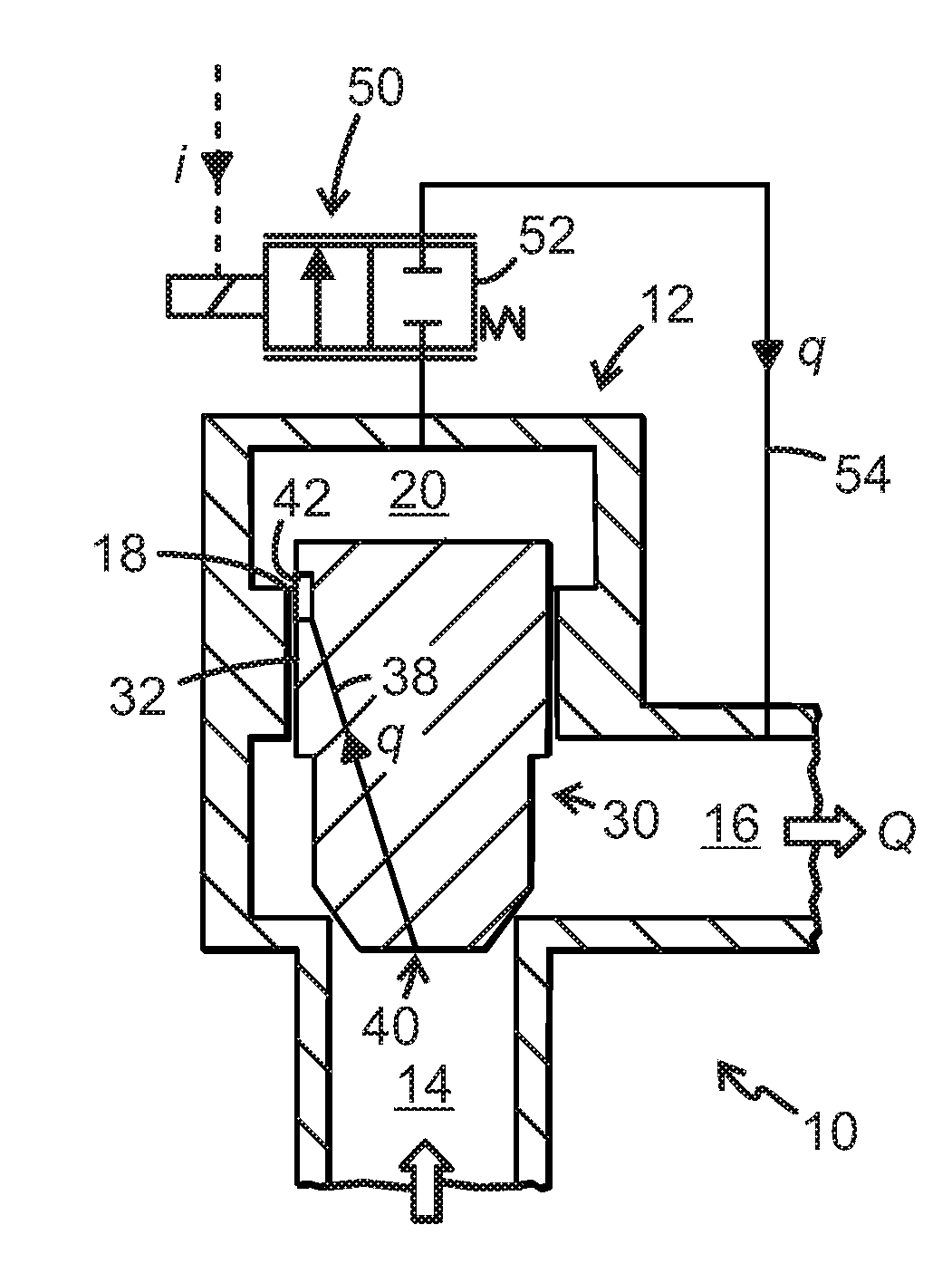
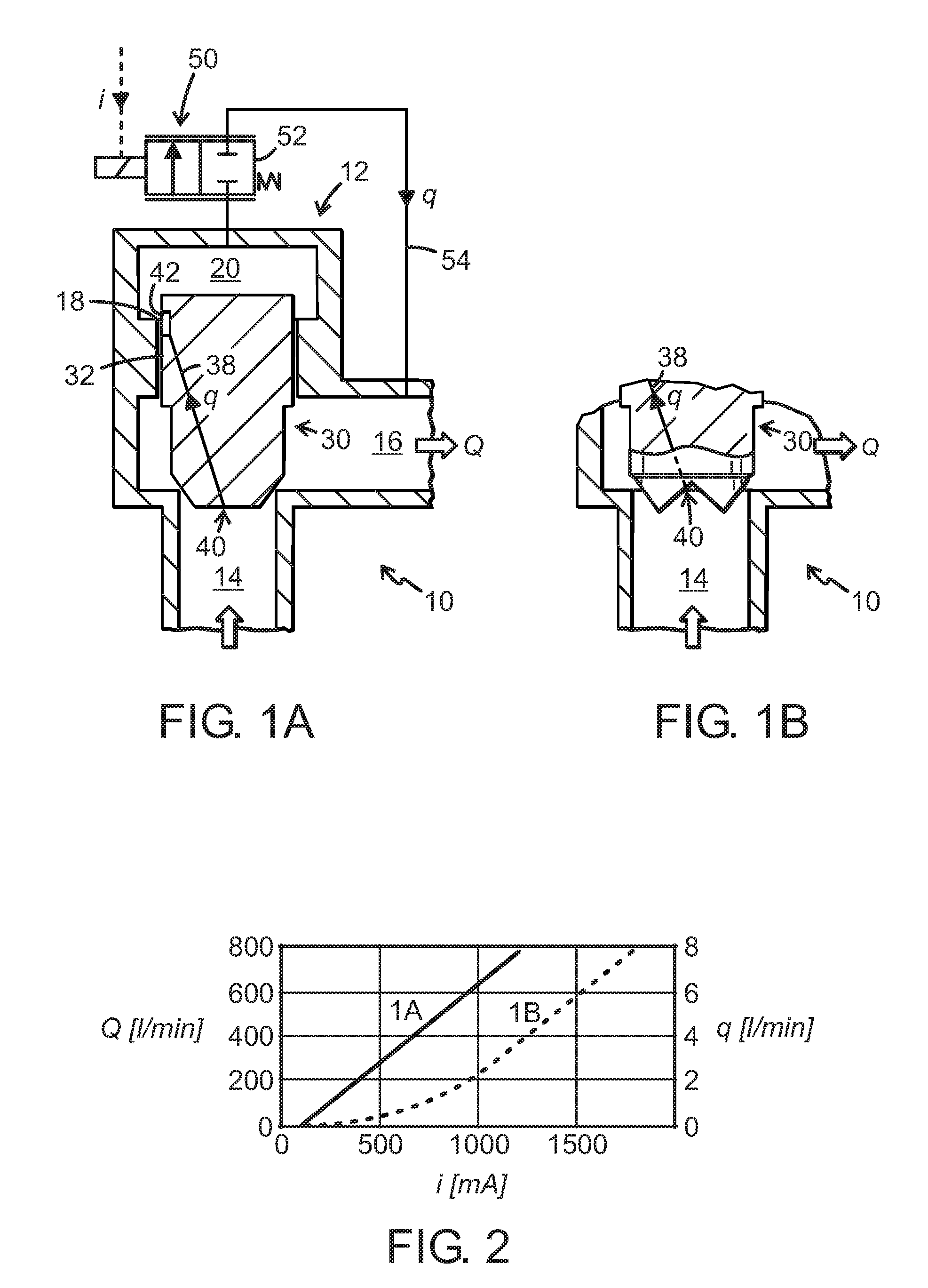
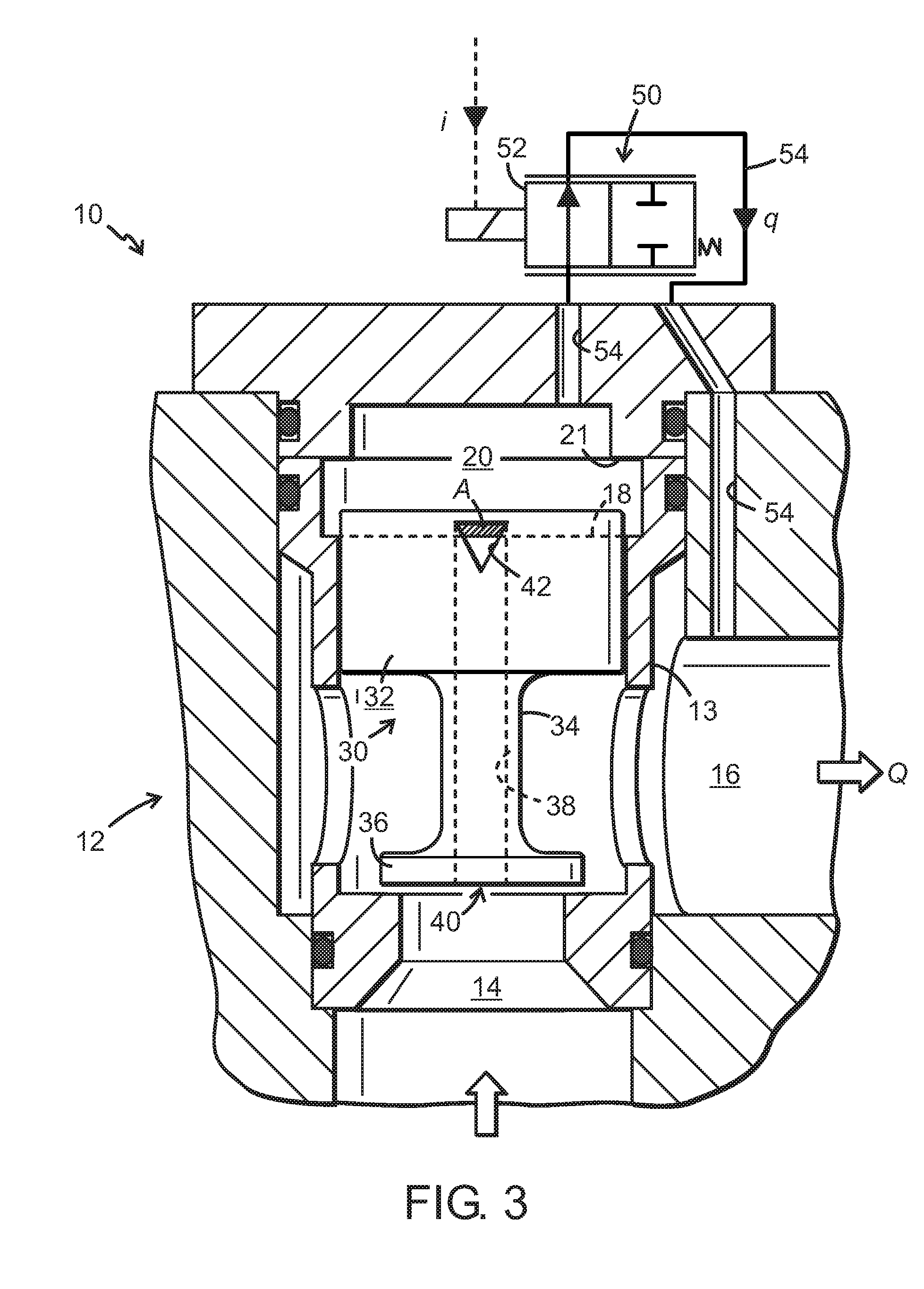
[0023]The fluid control valves 10 shown on the drawing are typically hydraulic power control valves comprising a valve housing 12 and a valve body 30 slidably received in the valve housing 12 for controlling a main flow Q of a pressurized fluid between an inlet port 14 and an outlet port 16 defined in the valve housing 12. The flow closing and opening end of the valve body 30 may optionally and independent of the invention be of different types: In the prior art embodiment of FIG. 1A, the valve body 30 is of a poppet seat valve type having a frusto-conical closing end. In the prior art embodiment of FIG. 1B, the valve body 30 is of a combined poppet and spool type having a serrated or saw-tooth shaped closing end as mentioned in the foregoing. In the exemplary embodiment of FIGS. 3-6 according to the invention the valve body 30 is of the seat valve type, having a disc-shaped closing member 36. Accordingly, embodiments of the valve body of the invention may have any suitable type of ...


PUM


Abstract

A fluid control valve (10) comprising a valve housing (12), a valve body (30) having a peripheral surface (32) slidably supported for movement in an axial direction in the valve housing and a feedback circuit duct (38) in the valve body. The feedback circuit duct has a first end (40) communicating with a flow port (14) in the housing and a second end (42) opening at the peripheral surface (32). The second end is capable of exposing a variable opening area (A) to a control chamber (20) in the housing and thereby subjecting the valve body to said movement by a resulting difference between pressure dependent forces acting on opposite surfaces of the valve body. According to the invention, the second end comprises an aperture (42) having a peripheral width (w) that varies at least over a portion proximate to the control chamber of an axial length of the aperture exposable to the control chamber.

Description

TECHNICAL FIELD[0001]The present invention relates to a fluid control valve comprising a valve housing and a valve body having a peripheral surface slidably supported for movement in an axial direction in the valve housing. A feedback circuit duct is provided in the valve body and has a first end and a second end. The first end communicates with a flow port in the housing and the second end opens at the peripheral surface of the valve body and is capable of exposing a variable opening area to a control chamber in the housing and thereby subjecting the valve body to said movement by a resulting difference between pressure dependant forces acting on opposite surfaces of the valve body. The invention also relates to a valve body for such a fluid control valve.BACKGROUND[0002]A prior art valve of this type is the Valvistor® hydraulic feedback valve. The valve body of such valve is capable of amplifying a small pilot flow through the feedback duct that forms part of a pilot circuit. The ...

Claims


Application Information

Patent Timeline
IPC IPC(8): F16K31/12
CPCF16K31/406
Inventor LERNMARK, KRISTIANSUNDQVIST, HANS
Owner INAB AUTOMATION
Why Eureka
Try Eureka