
Needle cover assembly for a syringe

a technology of needle cover and syringe, which is applied in the direction of intravenous devices, infusion needles, infusion devices, etc., can solve the problems of reducing the likelihood of transferring blood or tissue-born diseases from one patient, the risk of accidental needle sticks,

Active Publication Date: 2009-12-03
STA MED
View PDF60 Cites 102 Cited by
  • Summary
  • Abstract
  • Description
  • Claims
  • Application Information

AI Technical Summary

Benefits of technology

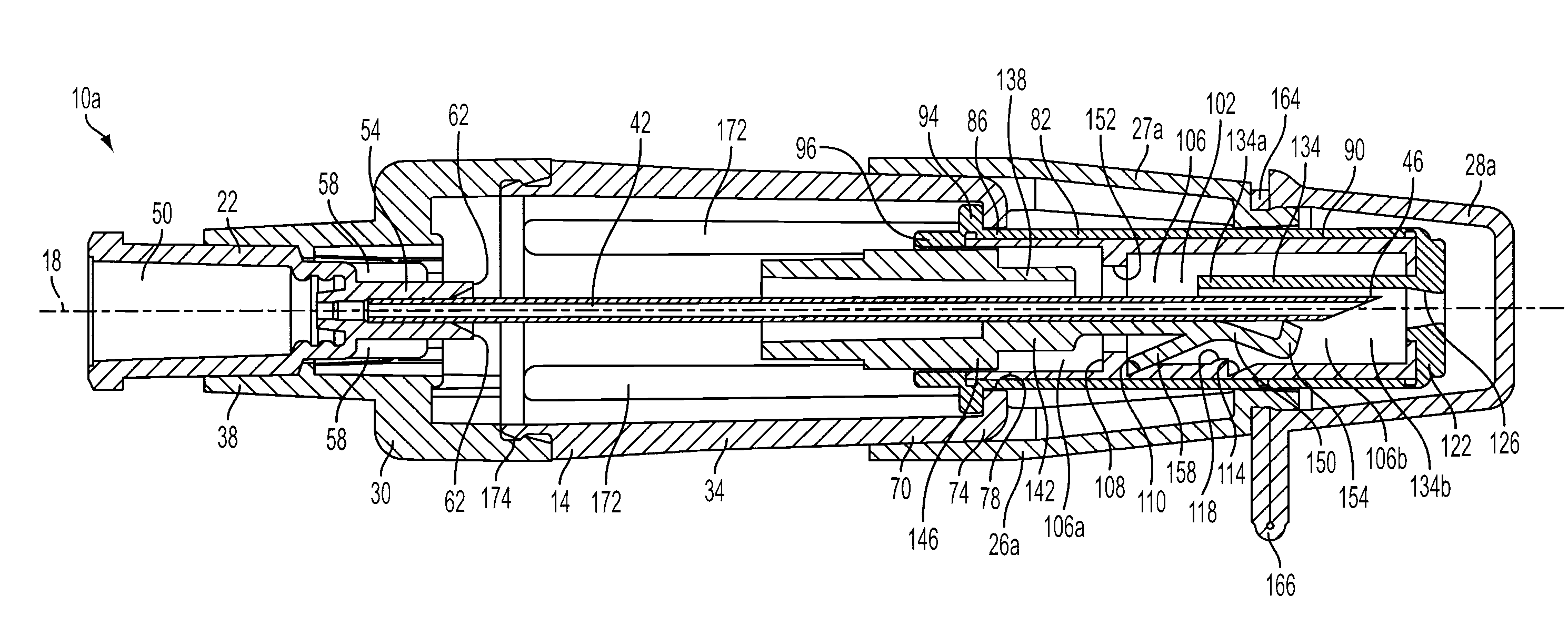
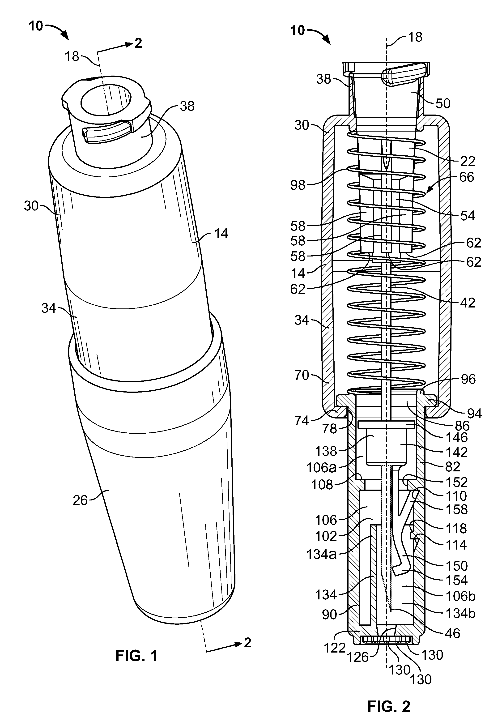
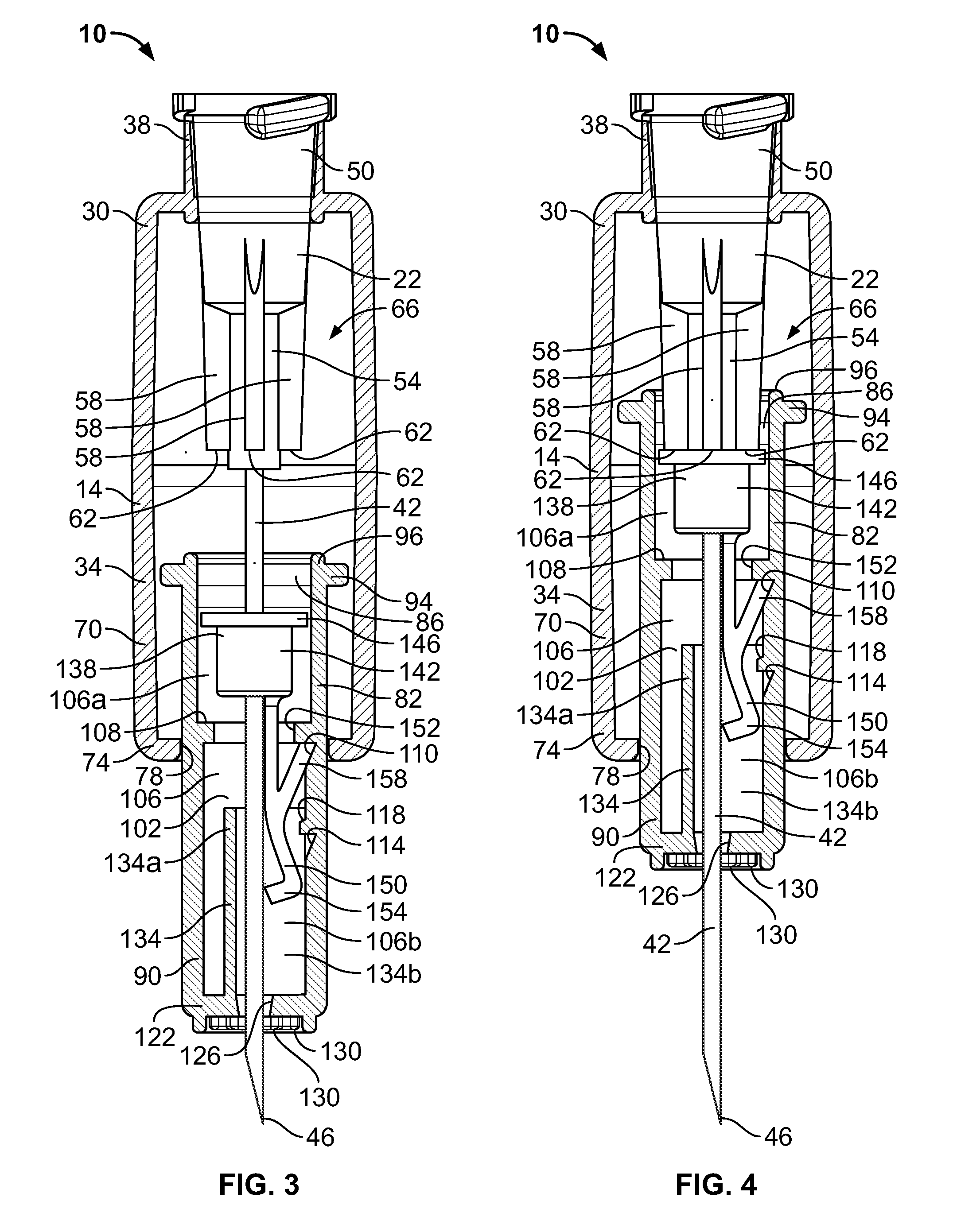
[0005]In some embodiments, the invention provides a needle cover apparatus for attachment to a syringe needle. The needle defines an axis and includes a distal tip. The needle cover apparatus includes a base and a sleeve. The sleeve includes a distal end defining an opening and is supported by the base for movement between an extended position in which the sleeve covers the distal tip of the needle and a retracted position in which the distal tip extends through the opening. The needle cover apparatus also includes a locking member that is supported by at least one of the base and the sleeve. The locking member is moveable relative to the sleeve and includes a locking portion that moves into axial alignment with the distal tip and the opening in response to movement of the sleeve from the retracted position to the extended position. Movement of the locking portion into axial alignment with the distal tip and the opening prevents subsequent movement of the sleeve to the retracted position.
[0007]In still other embodiments, the invention provides a needle cover apparatus for attachment to a syringe needle. The needle defines an axis and includes a distal tip. The needle cover apparatus includes a base that defines a central chamber. The central chamber receives a portion of the needle. The needle cover apparatus also includes a sleeve that is supported by the base and that is at least partially received by the central chamber. The sleeve defines a needle chamber that receives the needle. The sleeve also includes a distal end defining an opening that communicates with the needle chamber, and is axially moveable between an extended position in which the distal tip is positioned within the needle chamber and does not extend into the opening, and a retracted position wherein the distal tip extends through the opening. The sleeve is biased toward the extended position. The needle cover apparatus also includes a locking member that is received by the needle chamber and that includes a body portion through which the needle extends. The locking member includes a resilient arm that extends distally from the body portion, and a locking portion that is formed at an end of the arm. The locking member is moveable relative to the sleeve between a first position and a second position. When the sleeve is in the extended position and the locking member is in the first position, the locking portion is offset from the axis and positioned proximally of the distal tip. When the sleeve is moved from the extended position to the retracted position, the locking member moves from the first position to the second position. When the sleeve subsequently returns to the extended position with the locking member in the second position, the locking portion moves into alignment with the axis and is positioned distally of the distal tip, which prevents subsequent movement of the distal tip through the opening.

Problems solved by technology

This removal and replacement procedure creates a risk of accidental needle sticks.
This procedure reduces the likelihood of transferring blood or tissue-born diseases from one patient to another.

Method used


Image

  • Needle cover assembly for a syringe
  • Needle cover assembly for a syringe
  • Needle cover assembly for a syringe

Examples


Embodiment Construction

[0022]It is to be understood that the invention is not limited in its application to the details of construction and the arrangements of the components set forth in the following description or embodiments, or illustrated in the drawings. The invention is capable of other embodiments and of being practiced or being carried out in various ways. Also, it is to be understood that the phraseology and terminology used herein is for the purpose of description and should not be regarded as limiting.

[0023]FIG. 1 illustrates a needle cover assembly 10 that may be removably coupled to a standard or specially configured syringe assembly (not shown). The cover assembly 10 includes features and components, discussed below in detail, that generally hide the needle from view before, during, and after an injection procedure, thereby reducing or alleviating at least some anxiety or fear that might otherwise be felt by certain patients or other individuals upon seeing the exposed needle. The cover as...


PUM


Abstract

A single-use cover assembly that obscures a substantial majority or an entirety of an injection needle from view before, during, and after an injection procedure. The cover assembly includes a housing and a needle sleeve that retracts and extends by sliding axially within the housing. The needle sleeve carries a locking collar that moves from a first position to a second position once the needle sleeve is fully retracted. In the first position the locking collar allows retraction of the needle sleeve from a fully extended position. In the second position, a portion of the locking collar covers a tip of the needle, thereby preventing retraction of the needle sleeve from the fully extended position.

Description

CROSS REFERENCE TO RELATED APPLICATIONS[0001]This application claims the benefit of and priority to U.S. Provisional Patent Application Nos. 61 / 058,165 and 61 / 138,786 filed Jun. 2, 2008 and Dec. 18, 2008, respectively. The entire contents of each of these applications are hereby incorporated by reference.BACKGROUND OF THE INVENTION[0002]The present invention relates to needle covers and needle cover assemblies for syringes.[0003]Syringes are used throughout the medical industry for the injection and withdrawal of a wide variety of fluids and solutions into and from the human body. Because of the numerous potential hazards associated with the handling and manipulation of bodily fluids, and particularly blood, there are a number of known safety features that are frequently incorporated into various types of syringes and syringe needles. For example, many syringe needles are provided with a removable cap that generally prevents needle sticks while the cover is in place. When the cap is...

Claims


Application Information

Patent Timeline
IPC IPC(8): A61M5/32
CPCA61M5/3202A61M5/326A61M5/3213A61M2005/3247A61M2005/3267A61M5/422A61M2005/325
Inventor RUBINSTEIN, SERGIOROSENBERG, SAMUEL KANOSKYSTEPKE, RUSSELL R.MAZURSKY, RICHARDHERLITZ, TODDHARKER, JOSHGODFREY, MARK W.JOKELA, STEPHEN M.
Owner STA MED
Learn More