
Folding assembly and foldaway table

a folding table and folding mechanism technology, applied in the field of folding mechanism and folding table of furniture, can solve problems such as unstable tables, and achieve the effects of simple structure, less rods, and reduced cos

Active Publication Date: 2009-12-03
NEW TEC INTEGRATION (XIAMEN) CO LTD
View PDF14 Cites 6 Cited by
  • Summary
  • Abstract
  • Description
  • Claims
  • Application Information

AI Technical Summary

Benefits of technology

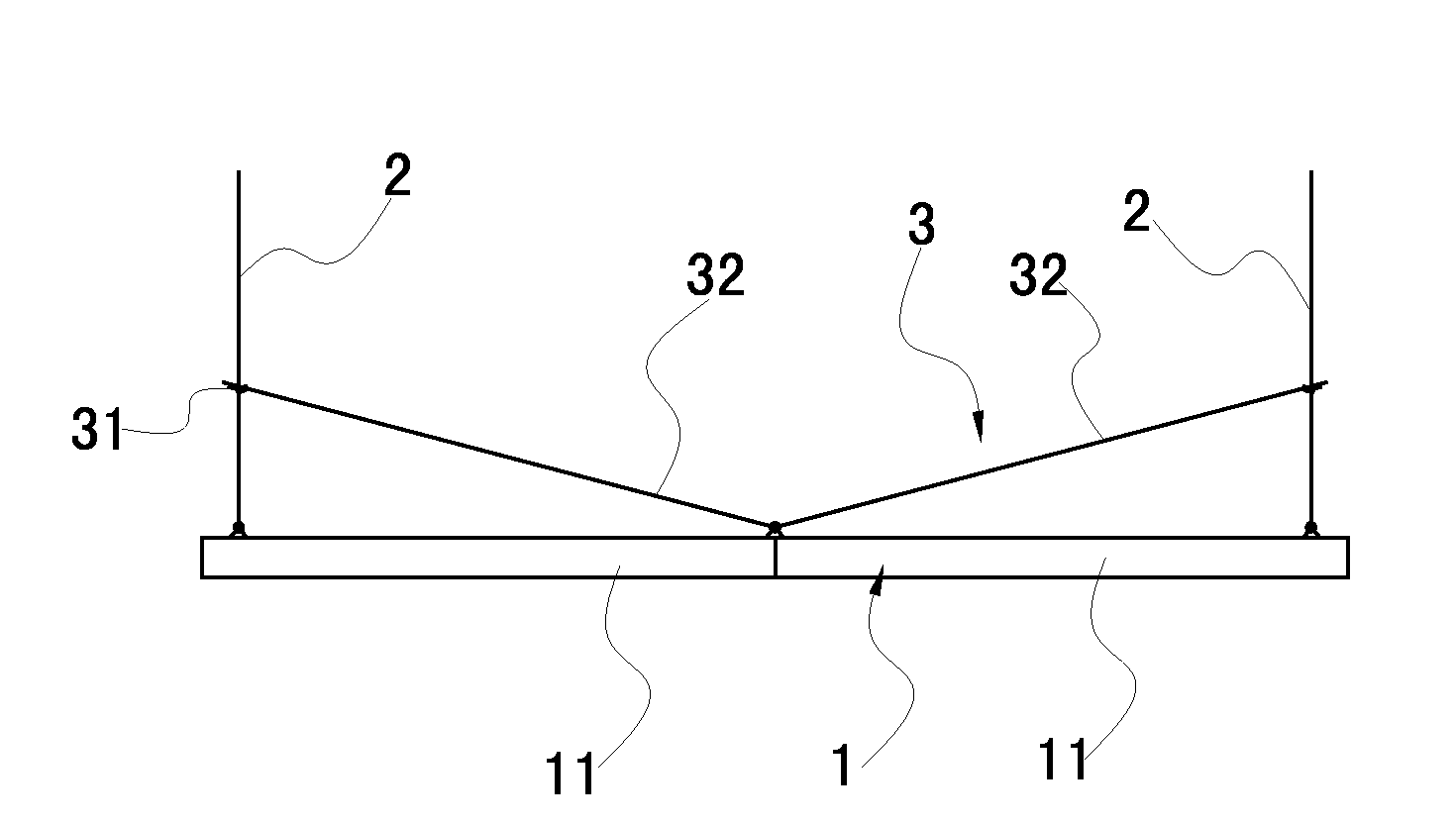
The present invention provides a folding mechanism and table with a simple structure, fewer rods, lower cost, and improved stability and folding speed. The folding mechanism includes a table top, a leg portion, and a supporting portion, with the supporting portion comprising a supporting rod and a locking member. The supporting rod is connected to the table top and the leg portion, and can rotate and slide in the process of folding or unfolding. The locking member is connected to the leg portion and can lock or release the position of the supporting rod. The folding mechanism is designed to have a preferred angle for pressing, a most laborsaving moment arm, and a high stable capability. The table with the folding mechanism has a simple structure, fewer rods, lower cost, and improved stability and folding speed.

Problems solved by technology

However, the first pivotal-connection portion and the second pivotal-connection portion of the supporting portion of the folding mechanism can rotate relative to each other, thus the mechanism has a complicated structure, many rods, high cost, unstable when forced and unstable structure; locked by the ring after being unfolded make the locking unstable, accordingly, the table is unstable.

Method used


Image

  • Folding assembly and foldaway table
  • Folding assembly and foldaway table
  • Folding assembly and foldaway table

Examples


embodiment 1

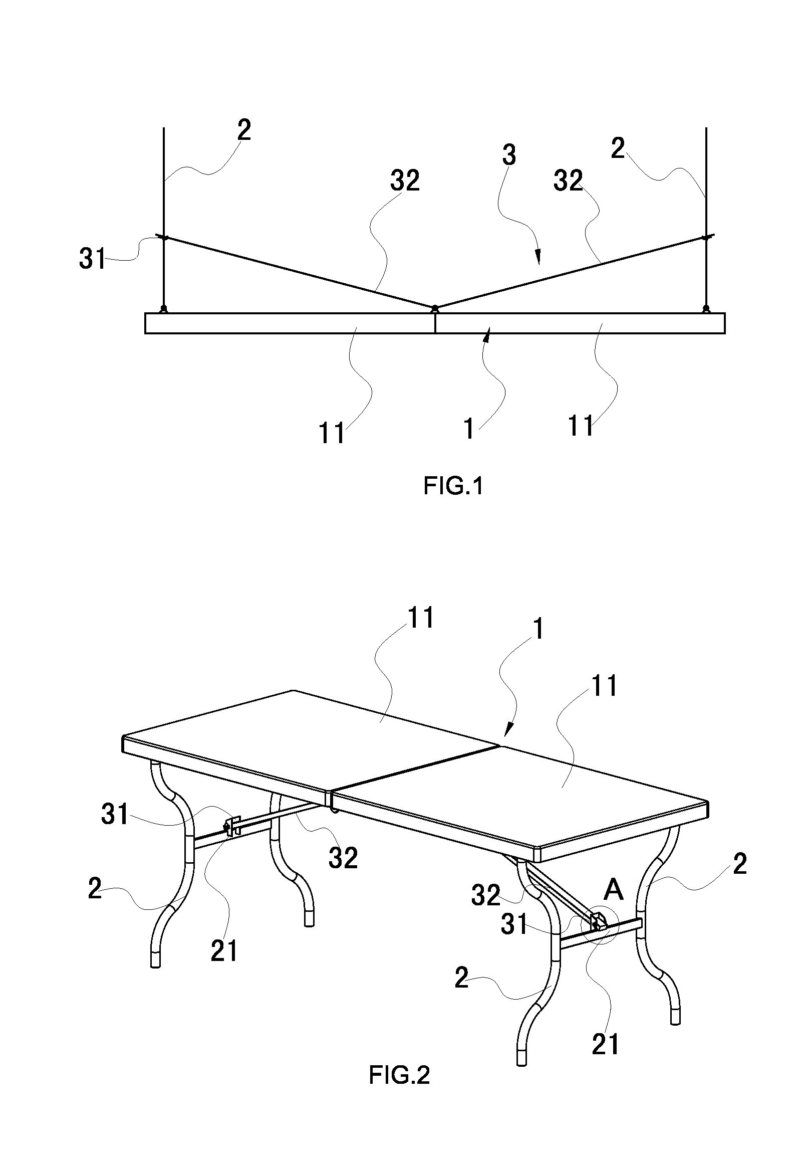
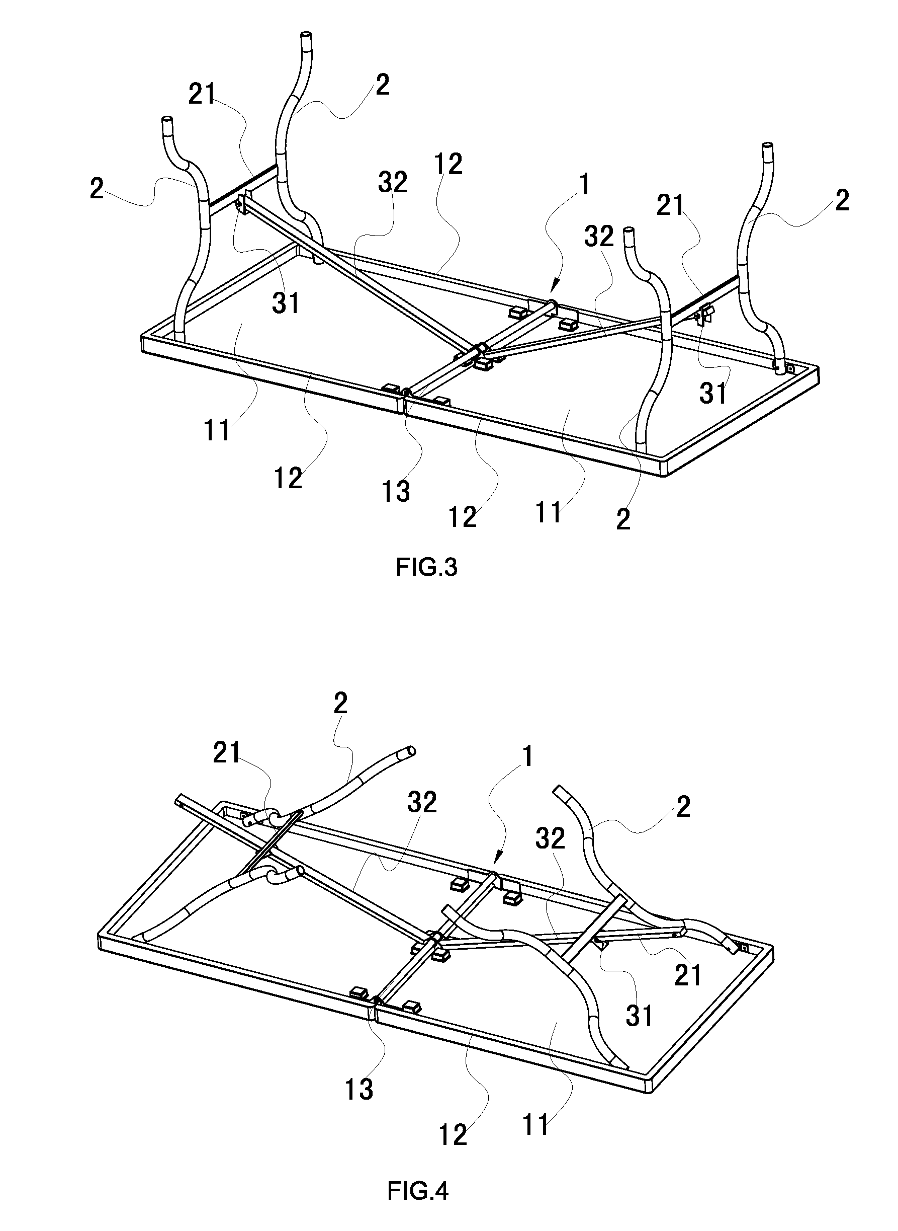
[0042]Referring to FIG. 1, FIG. 2 and FIG. 3, a folding table comprises a table top 1, four legs 2 and two supporting portion 3, the top of each leg 2 rotatably connected to the table top 1, the supporting portion 3 connected between the table top 1 and leg 2.

[0043]Referring to FIG. 3 and FIG. 7, the table top 1 comprises two vacuum molded boards 11 pivotally connected to each other by a central pivot 13 to let them can be folded in half. A clamping device is equipped for locking the position of the two vacuum-molded boards after being unfolded to let them be remained in a stable unfolded position. The vacuum-molded board comprising a plastic top plate, a plastic bottom plate, honeycombs, and lining, the top plate and the bottom plate fixedly adhered to the top and bottom of the honeycomb respectively, the lining sandwiched between the top plate and bottom plate and covering the honeycomb entirely or partially. The plastic top plate and the plastic bottom plate are all plastic compo...

embodiment 2

[0049]The difference of this embodiment to embodiment 1 is that: referring to FIG. 10, FIG. 11 and FIG. 12, the supporting portion 3 comprises a supporting rod 32 and a locking member 31. The locking member 31 comprises a rotate portion, a sliding sleeve 313 and a locking element 312, the rotate portion rotatably connected to the fixing rod 21, the sliding sleeve 313 fixed to the rotate portion. Referring to FIG. 14 and FIG. 15, the sliding sleeve 313 has a locking hole 3115 which connected the inner side and the outer side of the sliding sleeve 313. the locking element 312 comprises an elastomer disposed in the supporting rod 32, a block disposed on the surface of the elastomer, the block 3122 pass through the supporting rod 32 and insert in the locking hole 3115 by the elasticity force to lock the locking member 31 with supporting rod 32. The outer portion of the block 3122 which extended out the supporting rod 32 formed a sphere for automatically lock. Referring to FIG. 10, FIG. ...

embodiment 3

[0050]The difference of this embodiment to embodiment 1 is that: referring to FIG. 16, two pivots disposed in the bottom of the table top 1. the first end of the supporting rod 32 pivotally connected to the corresponding pivot 14 and the other end pass through the sliding sleeve 313, then locked by locking element 312 when reach unfolded position.


PUM


Abstract

A folding mechanism comprising a table top (1), a leg portion (2) and a supporting portion (3), said supporting portion comprising at least a supporting rod (32) and a locking member (31) connected to said leg portion, one end of said supporting rod rotatably connected to the lower surface of the tabled top and the other end connected to the locking member, the supporting rod formed a rotatable and slidable connection with the supporting portion so that a folding mechanism is formed by the table top, leg portion and the supporting portion. A folding table is also disclosed.

Description

FIELD OF THE INVENTION[0001]The present invention relates to a folding mechanism and folding table of furniture.BACKGROUND OF THE INVENTION[0002]Folding mechanism of foldable table in the market, such as ZL02259585.6 issued in Aug. 6, 2003 in CNPAT comprises a table top, a leg portion and a supporting portion, the upper portion of legs formed rotatable connection with the table top, the supporting portion comprises a first pivotally connecting with the leg portion, a second pivotal-connection portion for pivotally connecting with the table top and a ring, the first pivotal-connection portion pivotally connected with the second pivotal-connection portion, the table top, the leg portion, the first pivotal-connection portion and the second pivotal-connection portion formed a four-rod folding mechanism, after being unfolded, the folding mechanism is fixed in a unfolded position by the ring which limit the rotation between the first pivotal-connection portion and the second pivotal-conne...

Claims


Application Information

Patent Timeline
Patent Type & Authority Applications(United States)
IPC IPC(8): A47B3/08
CPCA47B3/0913A47B3/087
Inventor LENG, LUHAO
Owner NEW TEC INTEGRATION (XIAMEN) CO LTD
Learn More