
Machines and Methods for Removing Water From Air

a technology of air removal machine and air filter, which is applied in the direction of domestic cooling apparatus, separation process, heating type, etc., can solve the problems of increasing the cost of water production

Inactive Publication Date: 2009-12-03
SULLIVAN SHAUN E
View PDF94 Cites 20 Cited by
  • Summary
  • Abstract
  • Description
  • Claims
  • Application Information

AI Technical Summary

Problems solved by technology

While existing devices are capable of producing water from air, they commonly have limitations.
For example, existing devices may produce water at efficiency levels that are less than ideal.
As a result, the per-gallon water production cost may be prohibitively expensive for many circumstances.
The water production rates (e.g., gallons per day) may also be inadequate.
Or the machine may be excessively large, not portable manually, unnecessarily complex, and / or terribly expensive.

Method used


Image

  • Machines and Methods for Removing Water From Air
  • Machines and Methods for Removing Water From Air
  • Machines and Methods for Removing Water From Air

Examples


Embodiment Construction

[0015]The following detailed description should be read with reference to the drawings, in which like elements in different drawings are numbered identically. It will be understood that embodiments shown in the drawings and described herein are merely for illustrative purposes and are not intended to limit the invention to any embodiment. On the contrary, it is intended to cover all alternatives, modifications, and equivalents as may be included within the scope of the invention defined by the appended claims.

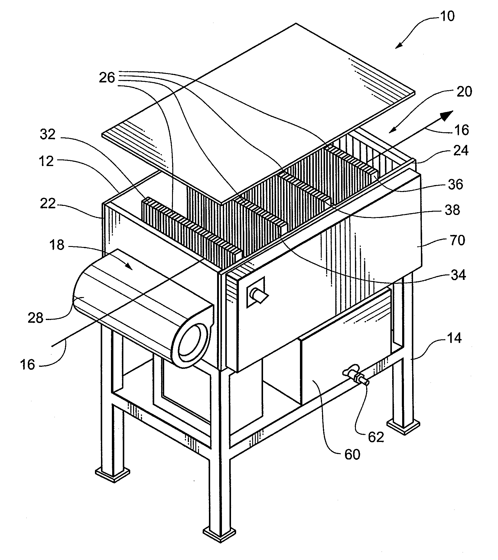
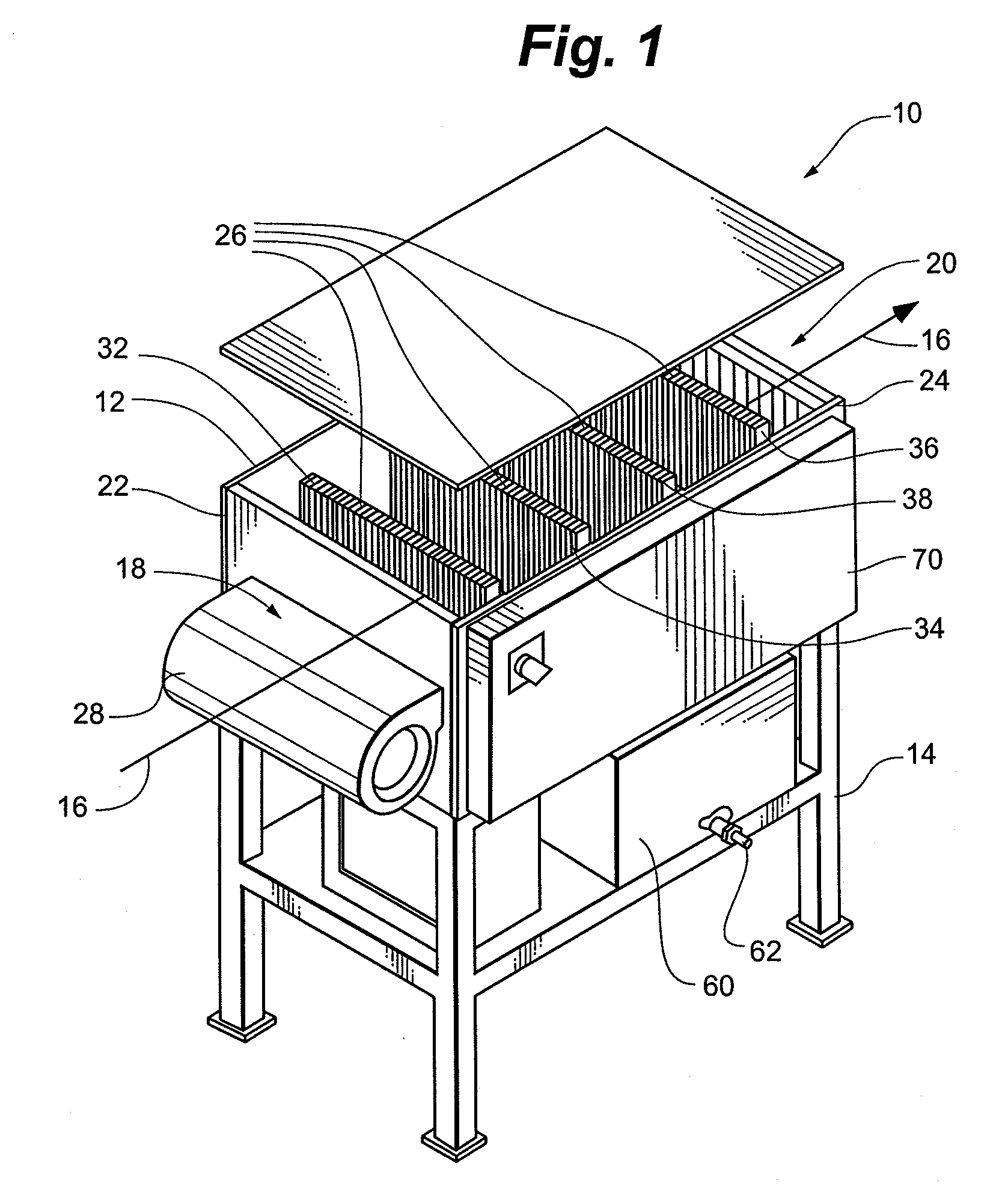
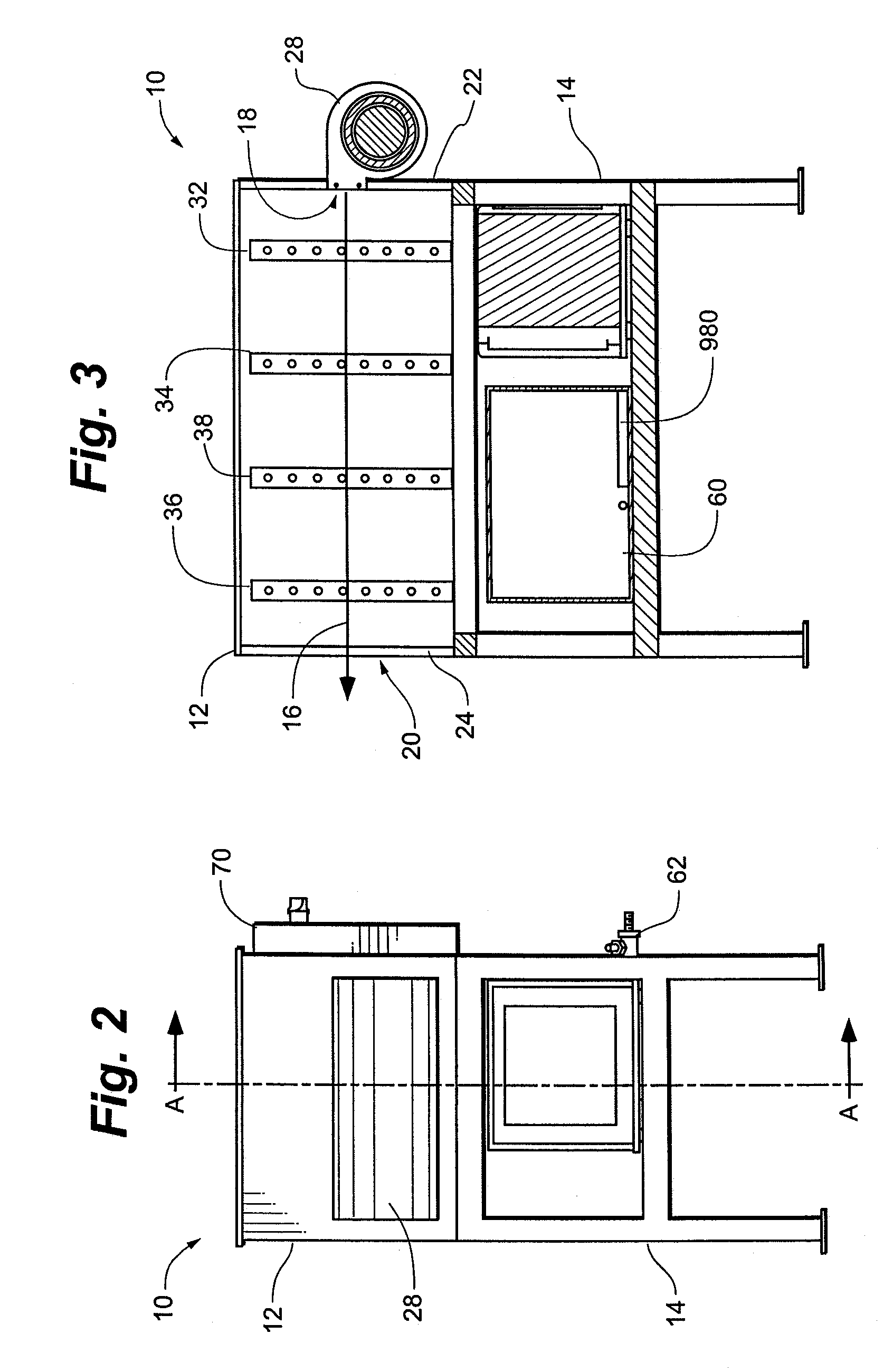
[0016]FIG. 1 illustrates a perspective view of a machine 10 for removing water from an air flow according to certain embodiments of the invention. The illustrated machine 10 comprises a housing 12 coupled to a frame 14, which is adapted to support the housing 12 upon a base, such as the ground, a floor of a building, a driveway, etc. The housing 12 can be configured in many different fashions, and the frame 14 may be omitted in some embodiments. The machine 10 has at least one ...


PUM

PropertyMeasurementUnit
Fractionaaaaaaaaaa
Temperatureaaaaaaaaaa
Flow rateaaaaaaaaaa

Abstract

The invention provides machines and methods for extracting water from atmospheric air. Also provided are bladed core heat exchangers.

Description

FIELD OF THE INVENTION[0001]The present invention relates generally to machines and methods for removing water from air. More specifically, the invention relates to machines and methods for removing water from an air flow to produce a supply of usable water.BACKGROUND[0002]Devices for extracting water from air are known. These devices may produce water for a variety of uses, such as human consumption. While existing devices are capable of producing water from air, they commonly have limitations. For example, existing devices may produce water at efficiency levels that are less than ideal. As a result, the per-gallon water production cost may be prohibitively expensive for many circumstances. The water production rates (e.g., gallons per day) may also be inadequate. Or the machine may be excessively large, not portable manually, unnecessarily complex, and / or terribly expensive.[0003]It would be desirable to provide machines and methods that can be used for improving and / or expanding ...

Claims


Application Information

Patent Timeline
IPC IPC(8): F25D21/14C02F1/28F25D17/06F24F3/14
CPCB01D5/0015B01D5/0036B01D5/006B01D7/02E03B3/28C02F1/18C02F1/22C02F1/32C02F1/041Y02A20/00
Inventor SULLIVAN, SHAUN E.
Owner SULLIVAN SHAUN E
Learn More