
Connector for the network device

a network device and connector technology, applied in the direction of coupling devices, two-part coupling devices, baseband system details, etc., can solve the problems of increased manufacturing cost of network devices and difficult circuit design, and achieve the effect of reducing interference between connecting ports and improving transmission efficiency of network devices

Inactive Publication Date: 2009-11-19
ZYXEL
View PDF7 Cites 2 Cited by
  • Summary
  • Abstract
  • Description
  • Claims
  • Application Information

AI Technical Summary

Benefits of technology

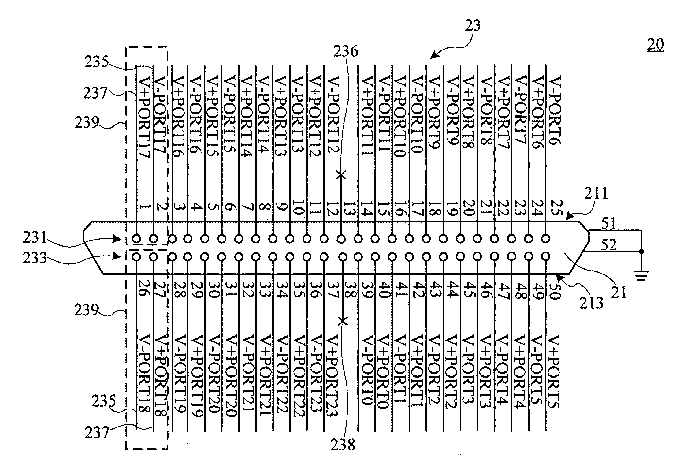
[0009]It is therefore a primary object of the present invention to provide a connector for the network device, adopting with horizontal symmetry type for combining pins to be the connecting ports, which are combined by a plurality of negative pins and positive pins, wherein each of negative pins is provided with the adjacent negative pin horizontally with the same row, thereby, the interference between connecting ports can be restrained, and further, the transmission efficiency of the network device can be improved.
[0010]It is a secondary object of the present invention to provide a connector for the network device, which is without additional circuit design or manufacturing cost, but the interference restraining function can be improved for the network device, thereby, it is convenient for manufacturing of the network device.
[0011]It is another object of the present invention to provide a connector for the network device, adopting with horizontal symmetry type for combining pins to be the connecting ports, wherein each of negative pins and positive pins are spread within the first row of pins and second row of pins evenly, thereby, the interval distance between each of pins can be enlarged for preventing the cross talk effect, wherein the pins are with the same polarity.

Problems solved by technology

Accordingly, the circuit design will be difficult and the manufacturing cost of the network device will be increased since the foregoing solutions are implemented.

Method used


Image

  • Connector for the network device
  • Connector for the network device
  • Connector for the network device

Examples


Embodiment Construction

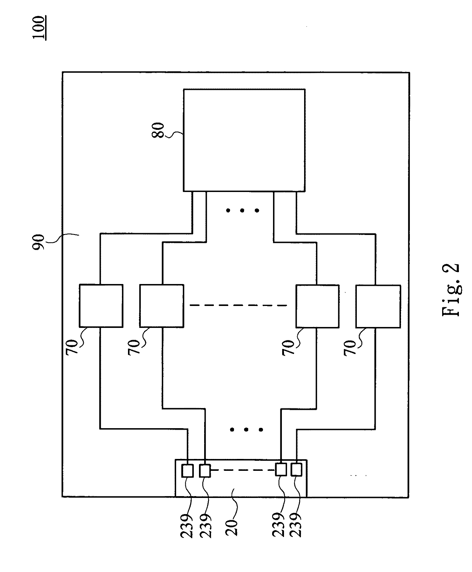
[0022]Referring to FIG. 2, a block diagram showing the structure of a network device according to the preferred embodiment of the present invention is disclosed. The network device 100 comprises a connector 20, a plurality of line drivers 70, and a process unit 80. The connector 20 comprises a plurality of connecting ports 239, wherein each of connecting ports 239 is connected to a corresponding line driver 70, and each of line drivers 70 is connected to the process unit 80, and further, the connector 20, line drivers 70, and process unit 80 are provided on a circuit board 90.

[0023]The process unit 80 is used for controlling each of line drivers 70 to drive the corresponding connecting port 239 in the connector 20, thereby, the network signal can be received and transmitted through the connecting ports 239, and the process unit 80 can process operation for the network signal.

[0024]The network device 100 is applied on an X Digital Subscriber Line (XDSL), such as a Very High Data Rate...


PUM


Abstract

A connector for the network device comprises a connecting body and a plurality of pins. The connecting body comprises a first side and a second side, and the pins comprise a first row of pins and a second row of pins, wherein the first row of pins are provided with the first side, and the second row of pins are provided with the second side, and further, both of which comprise a plurality of negative pins and positive pins, wherein the negative pins and positive pins are spread within the first row of pins and the second row of pins alternately and evenly. Each of negative pins and adjacent positive pins are combined to be a connecting port in turn with horizontal symmetry type, such that the interference between the connecting ports can be restrained efficiently, thereby, the transmission efficiency for the network device will be improved accordingly.

Description

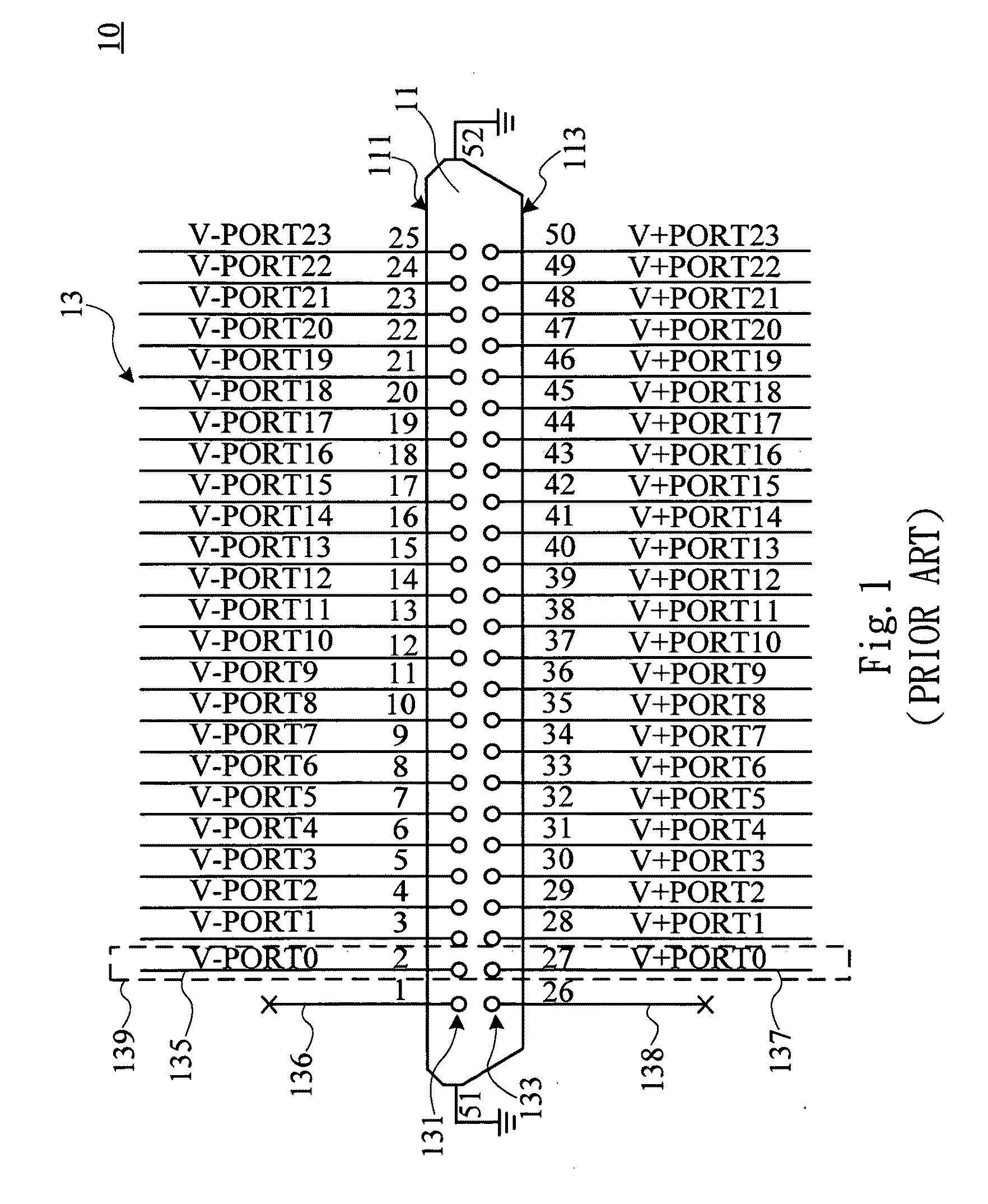
BACKGROUND OF THE INVENTION[0001]1. Technical Field[0002]The present invention is related to a connector for the network device, more particularly to a connector for the network device that can improve the transmission efficiency since the interference between the connecting ports has been restrained.[0003]2. Description of the Prior Art[0004]Referring to FIG. 1, a block diagram illustrating the structure of a prior art connector for the network device is showed. The connector 10 comprises a connecting body 11 and a plurality of pins 13. The connecting body 11 comprises a first side 111 and a second side 113, and the pins 13 comprise a first row of pins 131 and a second row of pins 133.[0005]The first row of pins 131 are provided with the first side 111, and the second row of pins 133 are provided with the second side 113, wherein the amounts of the first row of pins 131 and the second row of pins 133 are the same, and the first row of pins 131 comprise a plurality of negative pins ...

Claims


Application Information

Patent Timeline
IPC IPC(8): H01R24/04H01R24/58
CPCH01R13/6461H04L25/0264
Inventor LIAO, CHI-CHIHLAN, HUNG HSUN
Owner ZYXEL
Learn More