System for automatic testing of a digital x-ray detector

a technology of digital x-ray detector and automatic testing, which is applied in the field of radiography, can solve the problems of reducing the input signal, entailing a more complicated and expensive construction, and limited choice of radiographic screens that can be used in these x-ray detectors, and achieve the effect of reducing errors

Inactive Publication Date: 2009-11-19
ZAO IMPULSE
View PDF5 Cites 0 Cited by
  • Summary
  • Abstract
  • Description
  • Claims
  • Application Information

AI Technical Summary

Benefits of technology

[0007]The objective of the present invention is to create a self-diagnostic system of digital X-ray detector image sharpness setting that provides the technical result co

Problems solved by technology

Such fault is possible, for instance, at excessive mechanical loads experienced by a X-ray detector at incorrect transportation or improper operating methods.
Thus, choice of the radiographic screens that can be employed in these X-ray detectors is limited.
Thi

Method used


Image

  • System for automatic testing of a digital x-ray detector
  • System for automatic testing of a digital x-ray detector
  • System for automatic testing of a digital x-ray detector

Examples


Embodiment Construction

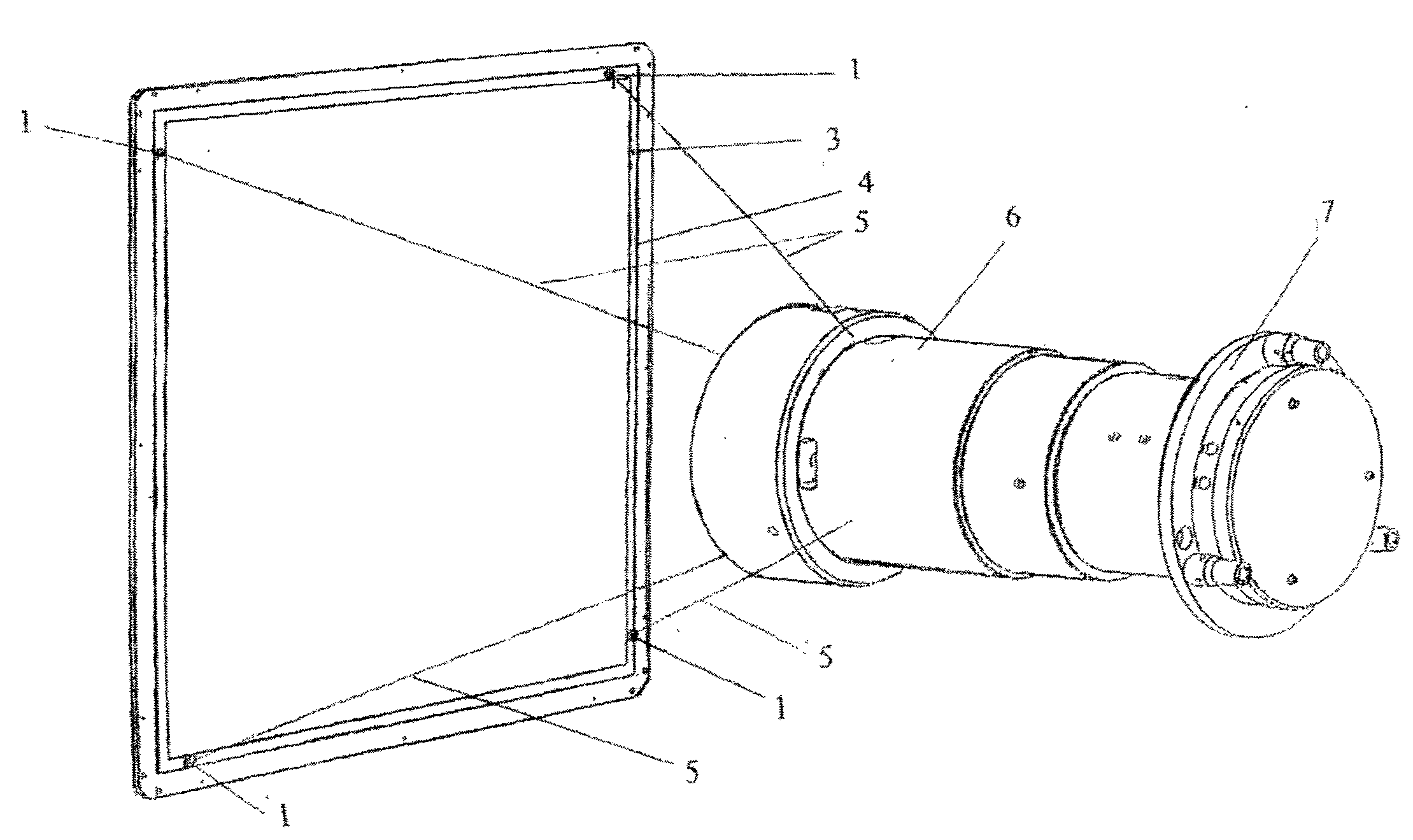
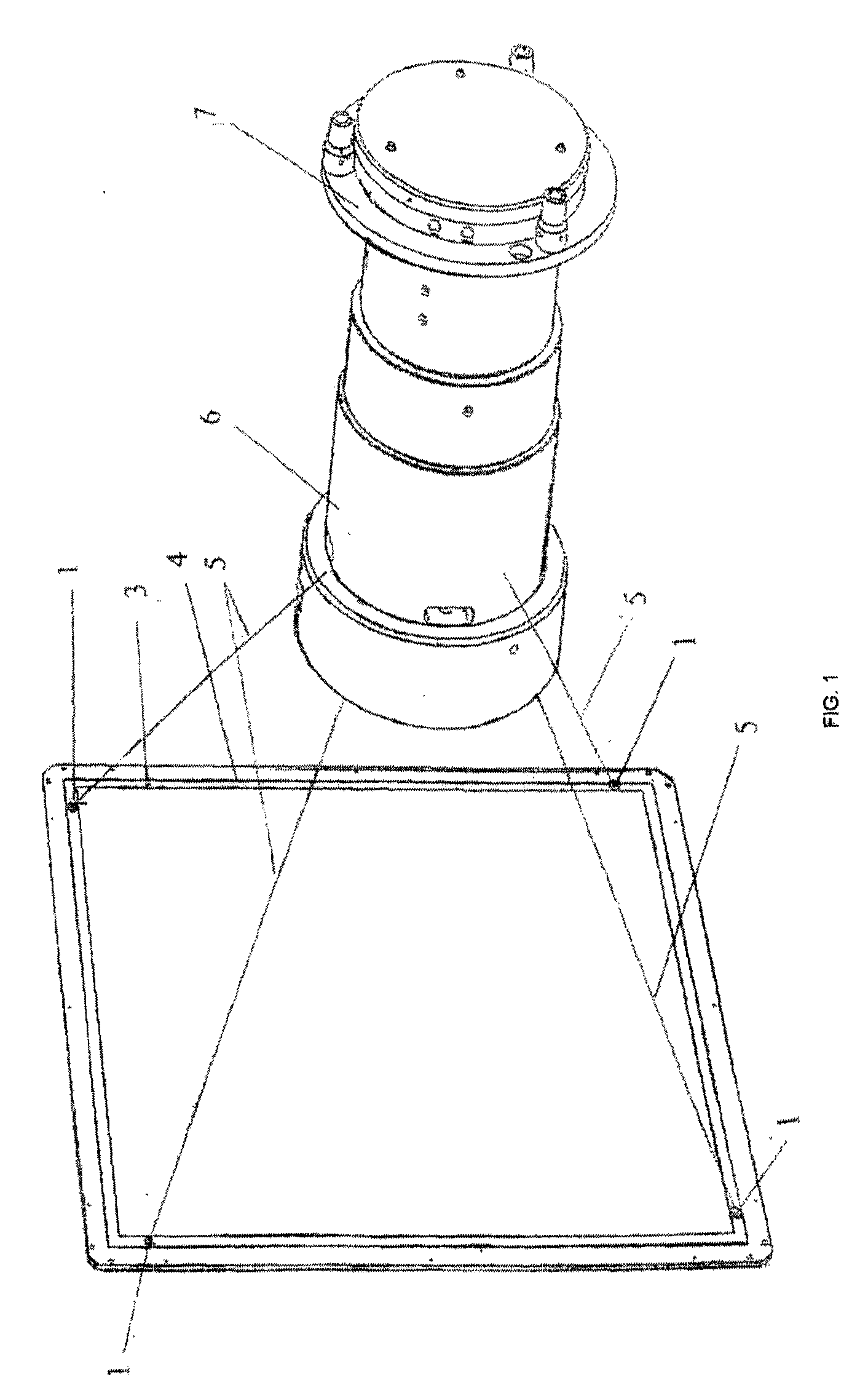
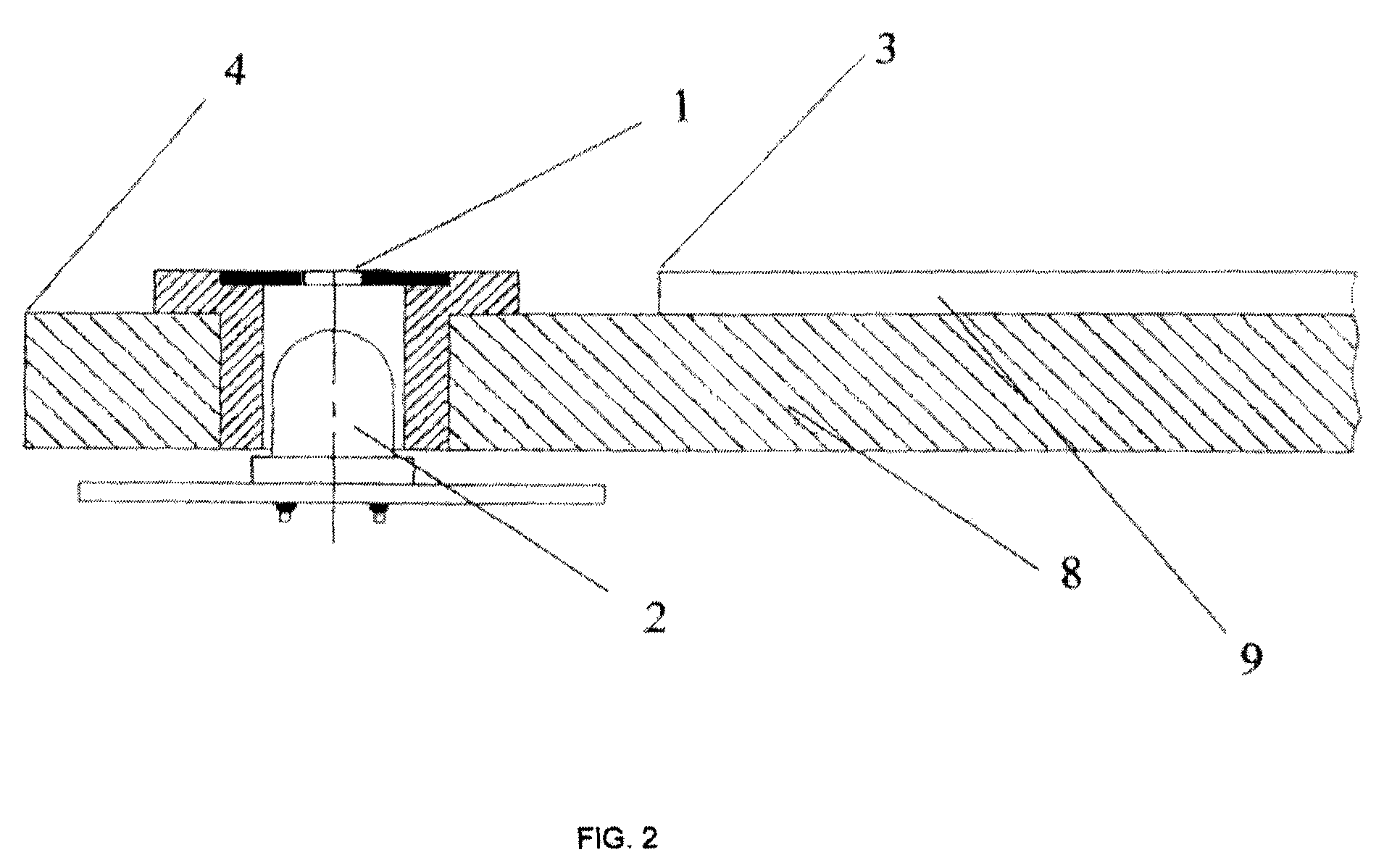
[0016]Figures in the drawings stand for:

[0017]1—test structure,

[0018]2—source of visible light,

[0019]3—boundary of the screen emitting surface,

[0020]4—visible field boundary in the radiographic screen plane,

[0021]5—the ray projecting a visible light source on the input lens of an objective lens,

[0022]6—objective lens,

[0023]7—image processing unit of a photosensitive CCD-matrix,

[0024]8—radiographic screen substrate,

[0025]9—radiographic screen.

[0026]In a digital X-ray detector, on the substrate 8 of the radiographic screen 9, in the corners, between boundary 3 of the radiographic screen 9 emitting surface (FIGS. 1 and 2) and visible field boundary 4, there are installed the sources 2 of visible light (hereinafter referred to as sources) based on light-emitting diodes with test structures 1. As shown in FIG. 2, every test structure is arranged in the direct path of rays from the said sources. Image of each test structure 1 is transferred by projecting rays 5 (FIG. 1) onto the input len...


PUM


Abstract

The present invention relates to radiography, including medical radiography, specifically to the apparatus for controlling the technical characteristics of digital radiographic devices, and is intended to maintain self-diagnostics of digital X-ray detectors. The self-diagnostics system of digital X-ray detectors comprises a radiographic screen 9 positioned in the radiation pathway from the radiographic source, an optical transfer system for transmitting an image from the screen 9 to the photosensitive CCD-matrix, whose output is connected to the image processing unit 7, and incorporates at least three test structures 1 installed in the emission plane of a radiographic screen 9. The technical result is achieved due to the fact that the test structures 1 are positioned outside the radiographic screen emitting surface and are provided with controlled sources of primary radiation installed so that each test structure 1 is located in the direct ray path from the said sources. FIGS. 1 and 2.

Description

RELATED APPLICATIONS[0001]This application is a Continuation of PCT application serial number PCT / RU2008 / 000307, filed on May 19, 2008, which is incorporated herein by reference in its entirety.FIELD OF THE INVENTION[0002]The present invention relates to radiography, including medical radiography, specifically to the apparatus for controlling the technical characteristics of digital radiographic devices, and can be used for testing of digital X-ray detectors.BACKGROUND OF THE INVENTION[0003]Digital detector of X-rays is an apparatus comprising a radiographic screen transforming the X-ray radiation into the visible one, an optical transfer system for transmitting an image to the photosensitive CCD-matrix (a group of photodetectors based on charge-coupled devices), which converts the image projected thereon into the digital signal. From the photosensitive CCD-matrix the digital signal passes into the image processing unit. Diagnostics of an investigated object is performed using the c...

Claims


Application Information

Patent Timeline
IPC IPC(8): G01D18/00
CPCG01T1/40
Inventor REBONI, VOLDEMAR O.BARANNIK, DMITRY A.
Owner ZAO IMPULSE
Why Eureka
Try Eureka