User-propelled wheeled vehicles

Inactive Publication Date: 2009-11-19
BURKE MICHAEL
View PDF7 Cites 13 Cited by
  • Summary
  • Abstract
  • Description
  • Claims
  • Application Information

AI Technical Summary

Benefits of technology

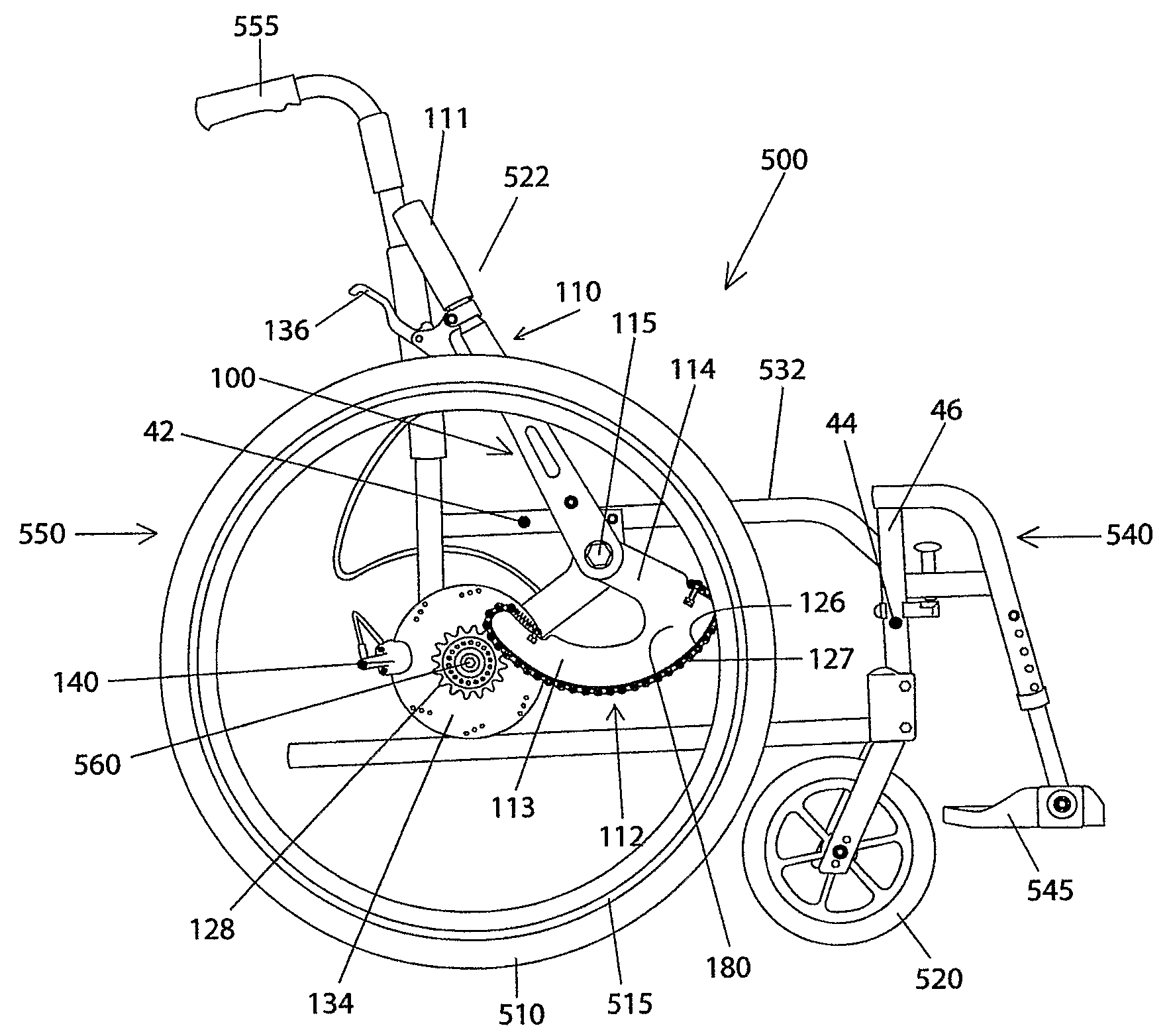
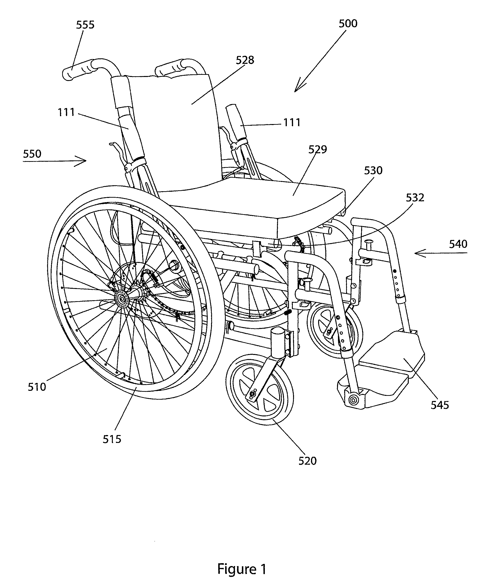
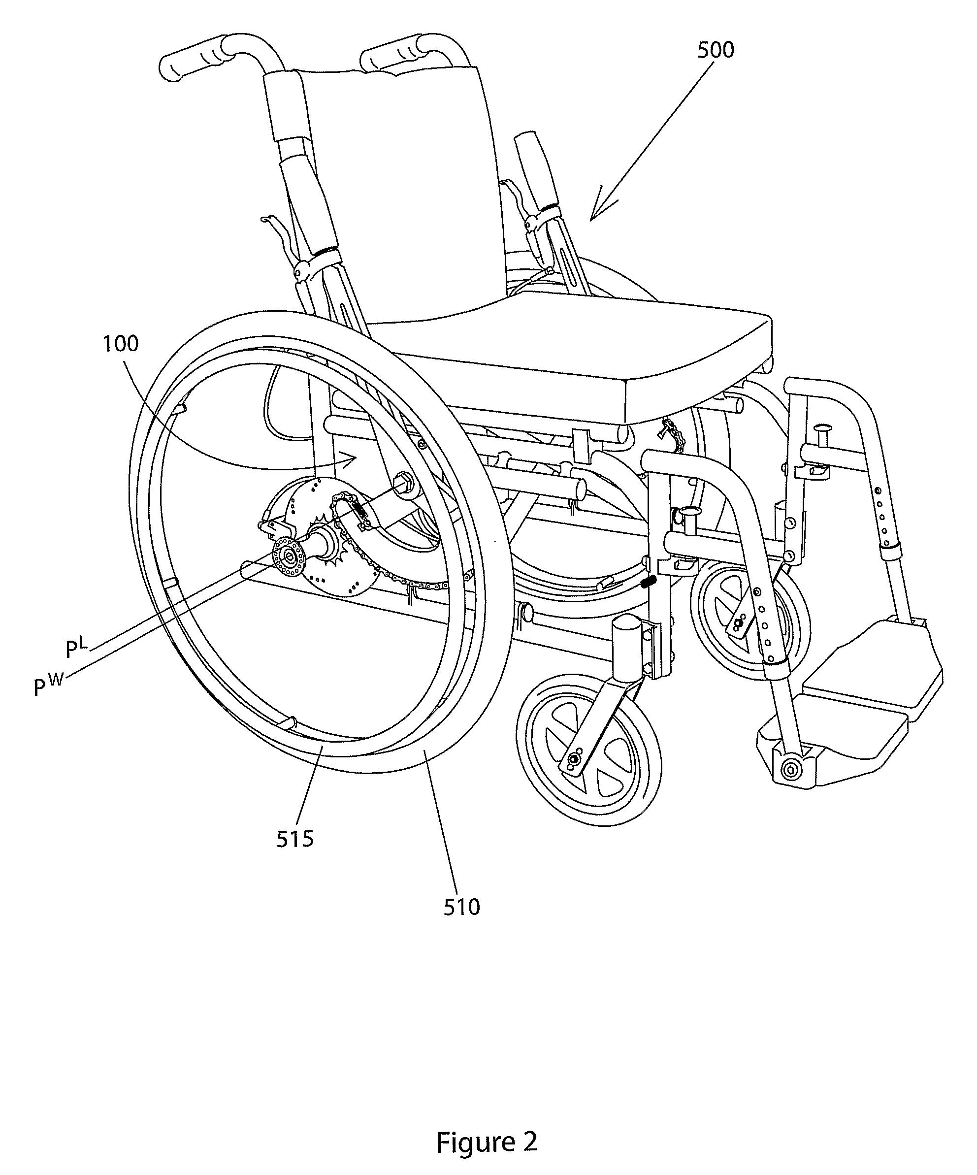
[0006]the lever having a user-operable portion on one side of the pivot axis and a drive end on the other side of the pivot axis, wherein the drive end is arcuately-reciprocatable with the user-operable portion and wherein the drive end includes a curved drive face, which includes a linear device for driving engagement with a sprocket wheel, which is co-axially mounted, between the wheel and the vehicle, on the hub of the wheel axle of the respective adjacent wheel, to drivingly co-operate with the respective vehicle wheel, to angularly move the wheel forwards and thereby to propel the vehicle forwards.
[0123]A stationary personal exercise machine according to the invention with a pair of levers, one on each side of a user support, may be propelled in a “Nordic Skiing” type of arm action, by alternately moving the lever arms repeatedly. This allows highly effective propulsion of the endless path device and also assists with stability.

Problems solved by technology

Also other vehicles are known having unwieldy mechanisms with which the user can drive the wheels forwards.
Such mechanisms are likely to be unreliable.
It is known to self-propel wheelchairs using the rims of large rear wheels or external rings attached thereto but in these instances, the wheelchair is difficult to move along fast as it is difficult for the user to move their own weight along while seated next to the driven wheels.

Method used


Image

  • User-propelled wheeled vehicles
  • User-propelled wheeled vehicles
  • User-propelled wheeled vehicles

Examples


second embodiment

[0228]With reference to FIGS. 14 to 30 of the drawings, a user-propelled wheeled vehicle according to this invention will now be described. In this embodiment the vehicle has the same lever driving arrangement on both its rear side wheels as the wheelchair just described. The vehicle will be referred to as a velocipede but it is especially suitable for use for sport and recreation and can also be called a human-powered go-kart. This vehicle has been unexpectedly found to be capable of highly effectively travelling over ground having variable gradient, especially sudden changes for example curbs.

[0229]Referring to FIG. 14, the velocipede (800) has a pair of relatively large, driven rear side wheels (810) and a single relatively small, front, non-driven wheel (820) for balancing the vehicle. Referring to FIG. 18, the velocipede has a welded framework (840) made from a spaced pair of longitudinal aluminium box-shaped members (844) and upper and lower spaced transverse aluminium box-sha...

third embodiment

[0294]In a third embodiment, a wheelchair (500′), shown in FIGS. 31 to 33, is constructed and operated similarly to the earlier described wheelchair: in this embodiment unitary drive levers with curved upper arms are provided. The wheelchair (500′) has a chassis frame (501′) having a left side (530′) and a right side (532′) and a pair of relatively large, rear, left and right driven wheels (595′, 596′) and a pair of relatively small, front, non-driven wheels (501′) for balancing the vehicle. The wheelchair has a seat (520′) for the user and a forward end (599′) and a rearward end (599′). Each pair of wheels is symmetrically disposed about the longitudinal centre line through the wheelchair. The basic wheelchair is again of the type manufactured by Medicare under the Enigma range.

[0295]The wheelchair further includes a rigid arm lever (590′) on each side. The lever has a curved upper user-operable portion, with a handle (525′) and an arcuate, lower drive end (550′) (also referred to ...

first embodiment

[0315]This generator has a base frame (40) with a pair of spaced side walls (42), and acts as a stand. A drive lever assembly is attached to each side wall of the frame in a manner corresponding to the Thus, a drive lever (43), a driven freewheel sprocket or gearwheel (44), and transmission shaft (50) are provided. These are the same, and in correspondingly the same position, on both side walls of the stand. A chair (41) is attached to the frame for supporting a person who can act on the levers to supply human power to be converted into electrical energy.

[0316]Each lever (43) has an elongate user-operable upper portion (44) with a handle (45) conveniently at its upper end, and a remote, lower drive end portion (46), also referred to herein as a crank, which is rigidly connected with the user-operable elongate upper portion (44). The elongate upper portion and the drive member are rigidly connected by a bolt and nut fixing (not shown), for movement one with the other; alternatively ...


PUM


Abstract

A seated user-propelled vehicle (500) can be propelled using levers (1000) acting on the rear side wheels (595). The levers are disposed between the wheels and the sides (530, 532) of the vehicle and can be moved together, separately or in turn. The levers have curved drive ends (113), the faces of which include a length of roller chain (127) to mesh with freewheels (555) on the hubs of the wheel axles (560) and are held in sufficient co-operation against the freewheels due to tensioning. The levers can be raised through approximately 90° in each drive stroke. Smooth and effective propulsion is obtained. Other uses of the drive levers are disclosed, including a go-kart, power generator, watercraft and personal exercise machine.

Description

TECHNICAL FIELD[0001]The present invention relates to improvements in user-propelled wheeled vehicles. User-propelled means throughout the specification propelled by an occupant of the vehicle.BACKGROUND OF THE INVENTION[0002]The Applicant has filed International patent application no. PCT / GB 2005 / 000111 for user-propelled wheeled vehicles. Disclosed therein are user-propelled wheeled vehicles in the form of a scooter and a wheelchair having in front a drive mechanism comprising a central front wheel and a combined steering column and push forward-pull back lever device, for turning the front wheel forwards, thereby propelling the vehicle forwards. The steering column assembly is attached to the scooter and to the wheelchair via an arrangement extending upwardly from the front of the wheelchair. This arrangement depends on the ability of the user to pull the steering column and on the reliability of the attachment between the drive mechanism and the rest of the vehicle.[0003]Also ot...

Claims


Application Information

Patent Timeline
IPC IPC(8): B62M1/00B62M1/04G05G1/08B62M1/24
CPCA61G5/023A61G5/025Y10T74/20492A61G2005/1051A61G5/10A61G5/1051
Inventor THOMAS, ENDA
Owner BURKE MICHAEL
Why Eureka
Try Eureka