
Mobile drilling rig

Active Publication Date: 2009-11-19
NAT OILWELL VARCO LP
View PDF35 Cites 84 Cited by
  • Summary
  • Abstract
  • Description
  • Claims
  • Application Information

AI Technical Summary

Benefits of technology

[0017]What follows are some of, but not all, the objects of this invention. In addition to the specific objects stated below for at least certain preferred embodiments of the invention, there are other objects and purposes which will be readily apparent to one of skill in this art who has the benefit of this i

Problems solved by technology

Currently, 3000 hp rigs are being made, but are not yet widely used.
Often large drilling rigs, e.g. in the Middle East, are transported between well sites by dismantling the rig into pieces that can be trucked between two well sites which can produce many time-consuming truckloads of rig components resulting in up to four additional weeks of rig downtime (the larger the capacity of the rig, the heavier the loads, and the number of loads also increases); and mounting the drilling module complete with mast on tires.
One drawback of a tire-mounted drilling module is tire load capacity and overall' rig height.
Anything taller than this will produce the potential for electrical arcing between the mast and the power lines if the rig is being towed on its tires.
Placing a wheeled moving system on certain rigs of this style may not be practical because it is not feasible to easily balance the wheel loads.
With such a system the the mast assembly can be relatively long when transporting it and the mast can be unstable during raising.

Method used


Image

  • Mobile drilling rig
  • Mobile drilling rig
  • Mobile drilling rig

Examples


Embodiment Construction

[0046]The present invention provides mobile drilling rigs, systems and methods for rig erection; and systems and methods for moving a drilling rig. This invention's teachings are applicable, inter alia, to any rig which has an erectable substructure.

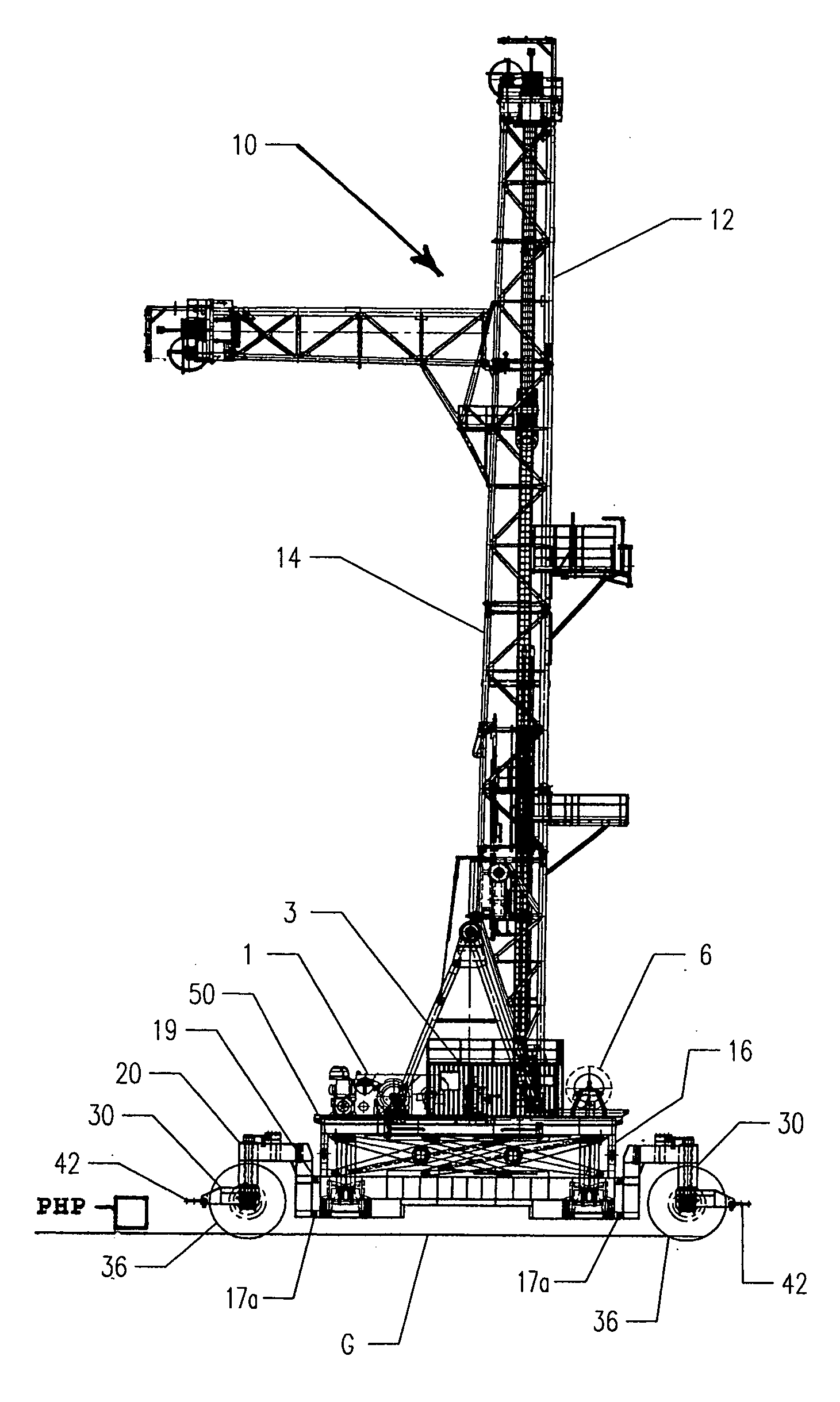
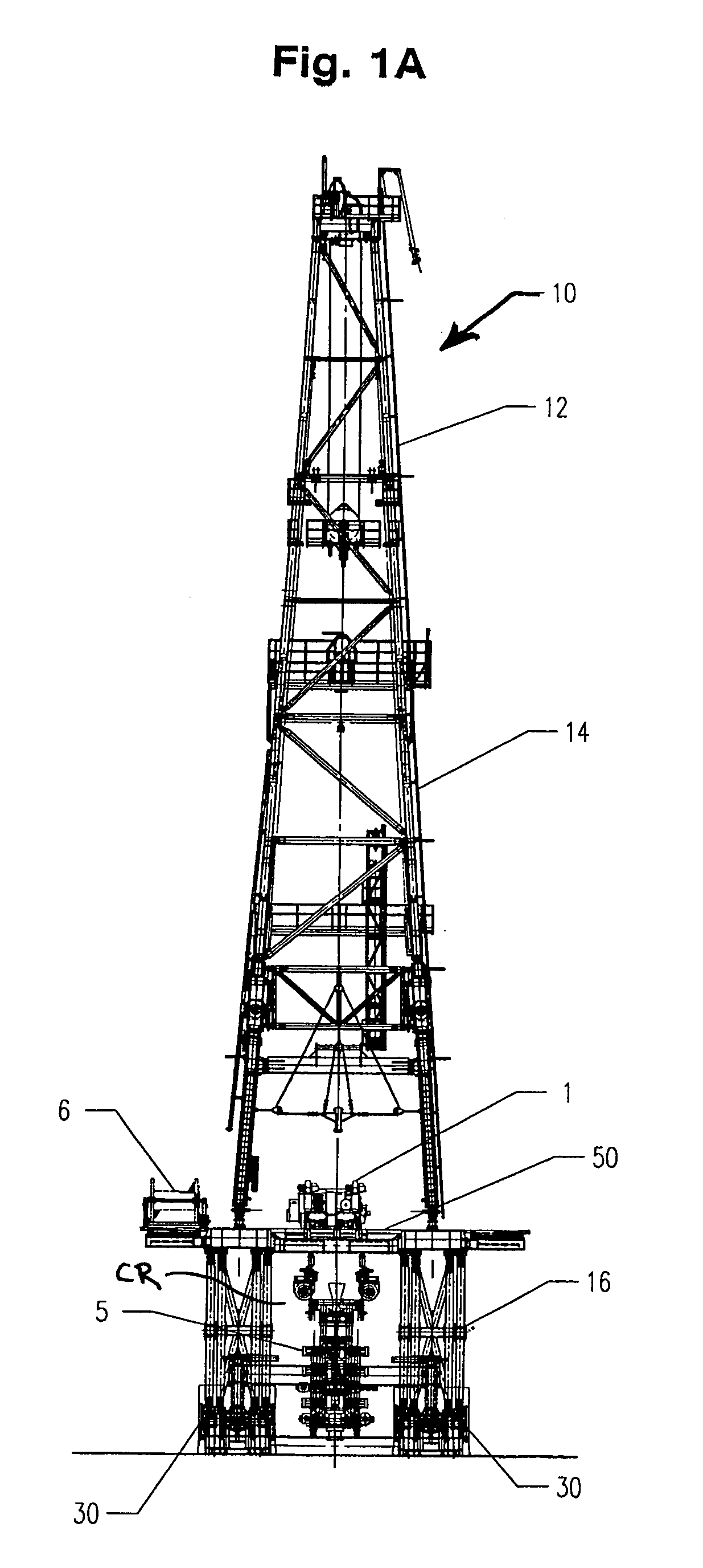
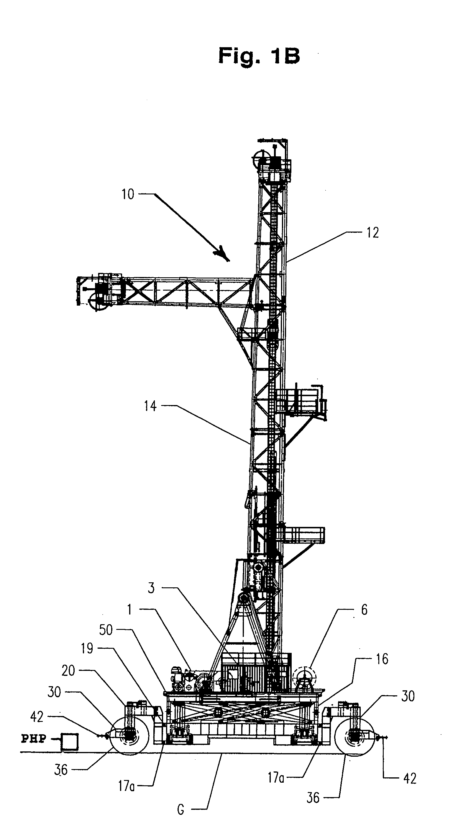
[0047]FIGS. 1A and 1B show a system 10 according to the present invention which includes a drilling rig 12 with a mast 14, a substructure 16, and movement apparatus 20 supporting the substructure 16, the mast 14, and related equipment and structure. The mast 14 may be, as shown, a tilt top mast, or it may be any suitable known mast. The substructure 16 is erectable from a lowered position as shown in FIG. 1B to a raised position as shown in FIGS. 1A and 1D. The system 10 includes typical rig equipment and, apparatuses, e.g., but not limited to, a drawworks 1, a rotary table 2 (see FIG. 1C), a driller cabin / doghouse 3, a setback floor 4, a BOP stack 5, a drill line spooler 6, and hydraulic catheads 8.

[0048]The movement apparatuses 20 (see...


PUM


Abstract

Mobile drilling rigs and methods for moving drilling rigs are disclosed which, in one aspect, include wheel assemblies connected to a rig which wheel assemblies are selectively movable from a rig drilling position to a rig movement position. This abstract is provided to comply with the rules requiring an abstract which will allow a searcher or other reader to quickly ascertain the subject matter of the technical disclosure and is submitted with the understanding that it will not be used to interpret or limit the scope or meaning of the claims, 37 C.F.R. 1.72(b).

Description

BACKGROUND OF THE INVENTION[0001]1. Field of the Invention[0002]This invention is directed to drilling rigs with erectable masts and substructures; in certain particular aspects, to such rigs that are mobile; and methods for moving a drilling rig.[0003]2. Description of Related Art[0004]The prior art discloses a variety of rigs used in drilling and various wellbore operations, including rigs that are mobile; for example, and not by way of limitation, U.S. Pat. Nos. 3,340,938; 3,807,109; 3,922,825; 3,942,593; 4,269,395; 4,290,495; 4,368,602; 4,489,526; 4,569,168; 4,837,992; 6,634,436; 6,523,319 and the references cited in these patents—all these patents incorporated fully herein for all purposes.[0005]In many land drilling operations, land rigs are delivered to a site, assembled and then disassembled; including, in many cases, raising a rig mast to a vertical operational position. Often as an oilfield becomes mature, wells are drilled deeper into the earth to obtain production. Oil r...

Claims


Application Information

Patent Timeline
IPC IPC(8): E21B12/00
CPCE21B7/023E21B7/02A61P25/06A61P25/08A61P9/00A61P9/10
Inventor KONDUC, KAMERON WAYNECALLAGHAN, JONATHAN DOUGLASANDERSON, TIMOTHY SCOTT
Owner NAT OILWELL VARCO LP
Learn More