
Method, apparatus and computer program product for determining a future time of a component

a component and future time technology, applied in the field of component health analysis, can solve the problems of needless replacement of healthy components, high cost of aircraft components, and catastrophic consequences

Active Publication Date: 2009-11-12
SIMMONDS PRECISION PRODS
View PDF7 Cites 38 Cited by
  • Summary
  • Abstract
  • Description
  • Claims
  • Application Information

AI Technical Summary

Benefits of technology

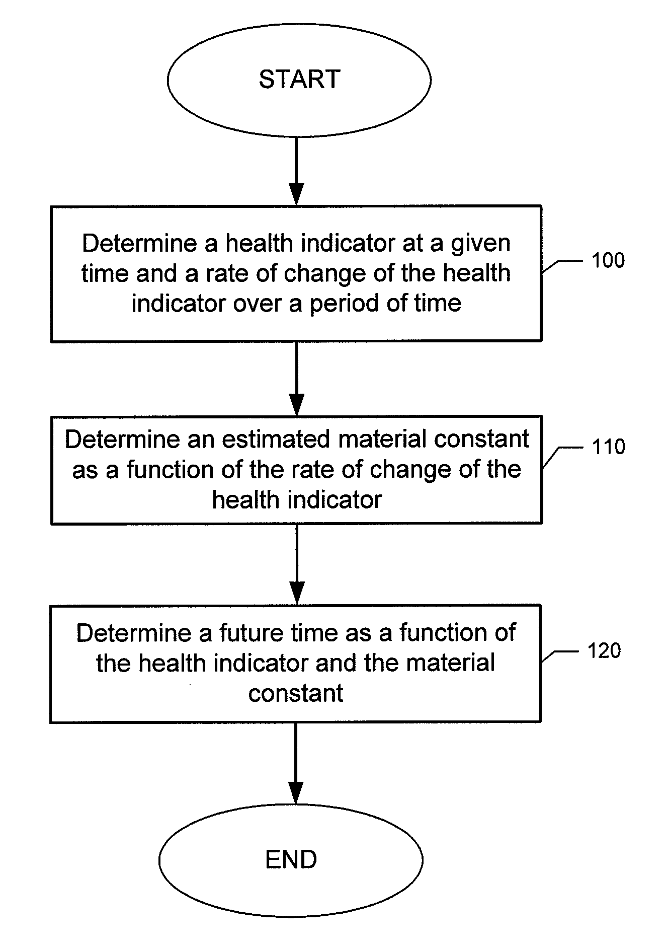
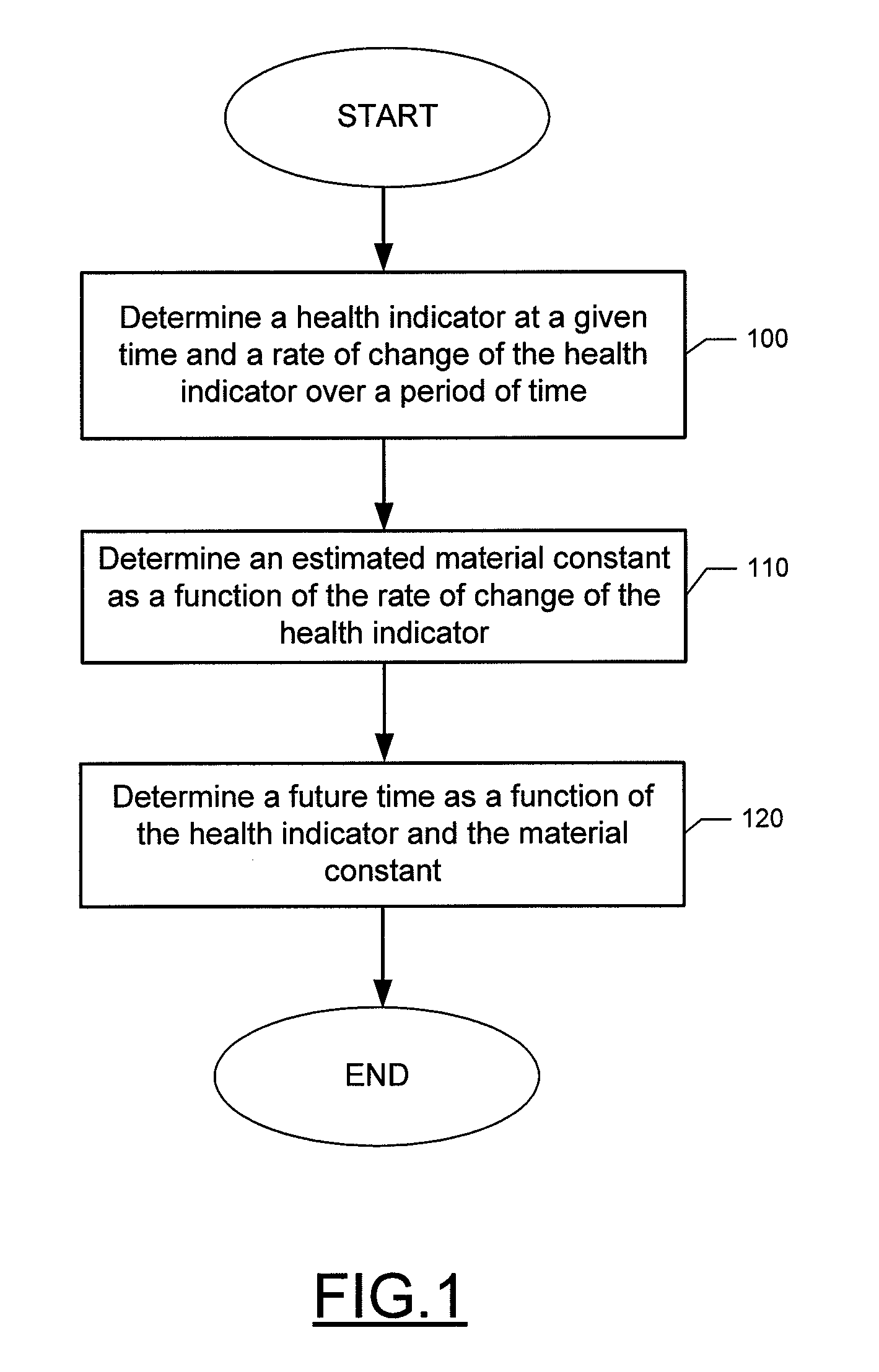
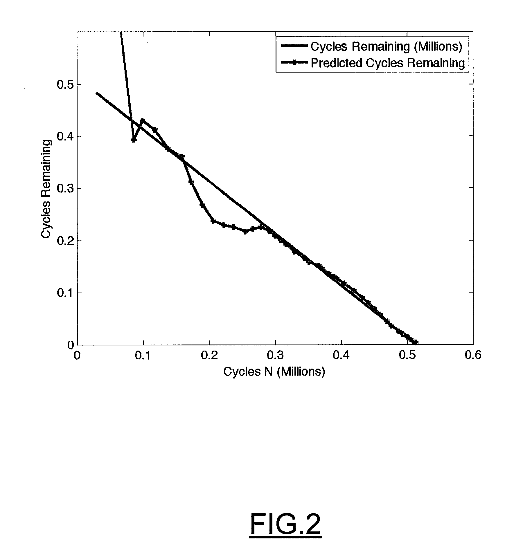
The present invention provides methods, apparatuses, and computer program products for determining the future time of a component that may require maintenance. This is done by using a health indicator and a material constant to estimate the number of fatigue cycles and the future time of the component. The future time can be compared against a threshold value to generate a notification if needed. The technical effect of this invention is to provide a more efficient and effective way to predict the time until maintenance is required for components, which can save time and money and prevent failures.

Problems solved by technology

The failure of components on an aircraft, and in particular moving components on a helicopter such as rotor transmission gears, can result in catastrophic consequences.
However, in some instances these replacement schedules may indicate replacement time intervals that are too aggressive, which can result in needless replacement of healthy components.
Since aircraft components are often quite expensive, the cost associated with needless replacement of healthy components can be relatively high.
Additionally, there is an operation cost of removing aircraft from service when in fact no maintenance is required.
Further, in some instances replacement schedules may indicate a replacement time interval that is too relaxed, such as when faulty or defective materials are installed, which can result in unexpected component failure and unscheduled maintenance.
Unscheduled maintenance results in lost revenue and decreased operational readiness, both which are important to aircraft operators.
Transmission of power to rotors and other moving components of an aircraft induce vibrations in the structures supporting the moving components.
Utilization of the vibration data to predict component failures is difficult.

Method used


Image

  • Method, apparatus and computer program product for determining a future time of a component
  • Method, apparatus and computer program product for determining a future time of a component
  • Method, apparatus and computer program product for determining a future time of a component

Examples


Embodiment Construction

[0012]Exemplary embodiments of the present invention will now be described more fully hereinafter with reference to the accompanying drawings, in which some, but not all embodiments of the present invention are shown. Indeed, the present invention may be embodied in many different forms and should not be construed as limited to the exemplary embodiments set forth herein; rather, these exemplary embodiments are provided so that this disclosure will satisfy applicable legal requirements. Like reference numerals refer to like elements throughout.

[0013]The methods, apparatuses and computer program products of exemplary embodiments of the present invention utilize health indicators to determine a future time which can be indicative of a time when some action can be taken with respect to a component. In some instances the future time can be described as a remaining useful life (RUL), or time until maintenance is required, for a particular component. As such, a functional relationship can ...


PUM


Abstract

A method, apparatus and computer program product are provided for determining a future time associated with a component, where the future time can be indicative that some action can be taken with respect to the component. In some embodiments, future time can be indicative of a component's remaining useful life or time until maintenance is required. The future time can be determined as a function of a health indicator and a material constant. In some exemplary embodiments of the present invention, the functional relationship between the future time, the health indicator and the material constant can be based on the functional relationship of Paris' law for fatigue crack growth.

Description

FIELD OF THE INVENTION[0001]Embodiments of the present invention relate generally to component health analysis, and, more particularly, relate to a method, apparatus and computer program product for determining a component's future time through statistical analysis.BACKGROUND OF THE INVENTION[0002]The failure of components on an aircraft, and in particular moving components on a helicopter such as rotor transmission gears, can result in catastrophic consequences. As such, aircraft are often kept on strict maintenance and component replacement schedules based on the hours of operation. These static, predetermined maintenance and replacement schedules are developed considering worst case component failure rates based on statistical data compilations and load cell testing. However, in some instances these replacement schedules may indicate replacement time intervals that are too aggressive, which can result in needless replacement of healthy components. Since aircraft components are of...

Claims


Application Information

Patent Timeline
Patent Type & Authority Applications(United States)
IPC IPC(8): G06F19/00
CPCG05B23/0283
Inventor BECHHOEFER, ERIC ROBERT
Owner SIMMONDS PRECISION PRODS
Learn More