
Cooling configuration for communication boards

Inactive Publication Date: 2009-11-12
MARVELL INT LTD
View PDF0 Cites 6 Cited by
  • Summary
  • Abstract
  • Description
  • Claims
  • Application Information

AI Technical Summary

Benefits of technology

[0007]One or more baffles may be utilized to control the rate of air flow through the various air spaces. One or more baffles may be utilized to control the air flow between the boards, thus increasing the rate of air flow above and below the boards. One or more baffles may also be located above and below the boards, such as to direct air towards the boards or towards particular components on the boards, such as those components requiring greater airflow to cool, and / or otherwise route air through those spaces.
[0008]In one embodiment, two boards are located in the housing in reverse orientations. Baffles are utilized to reduce the flow between the back sides of the boards which face one another, increasing the rate of air flow over the components at the opposing sides of the two boards.

Problems solved by technology

Unfortunately, this same mounting increases the likelihood of overheating of the board and makes the various components of the board, including the connectors, less accessible.
However, the close proximity of the equipment makes even more difficult the task of cooling the boards.
These solutions are not sufficiently effective, however, in situations such as those described above.

Method used


Image

  • Cooling configuration for communication boards
  • Cooling configuration for communication boards
  • Cooling configuration for communication boards

Examples


Embodiment Construction

[0021]In the following description, numerous specific details are set forth in order to provide a more thorough description of the present invention. It will be apparent, however, to one skilled in the art, that the present invention may be practiced without these specific details. In other instances, well-known features have not been described in detail so as not to obscure the invention.

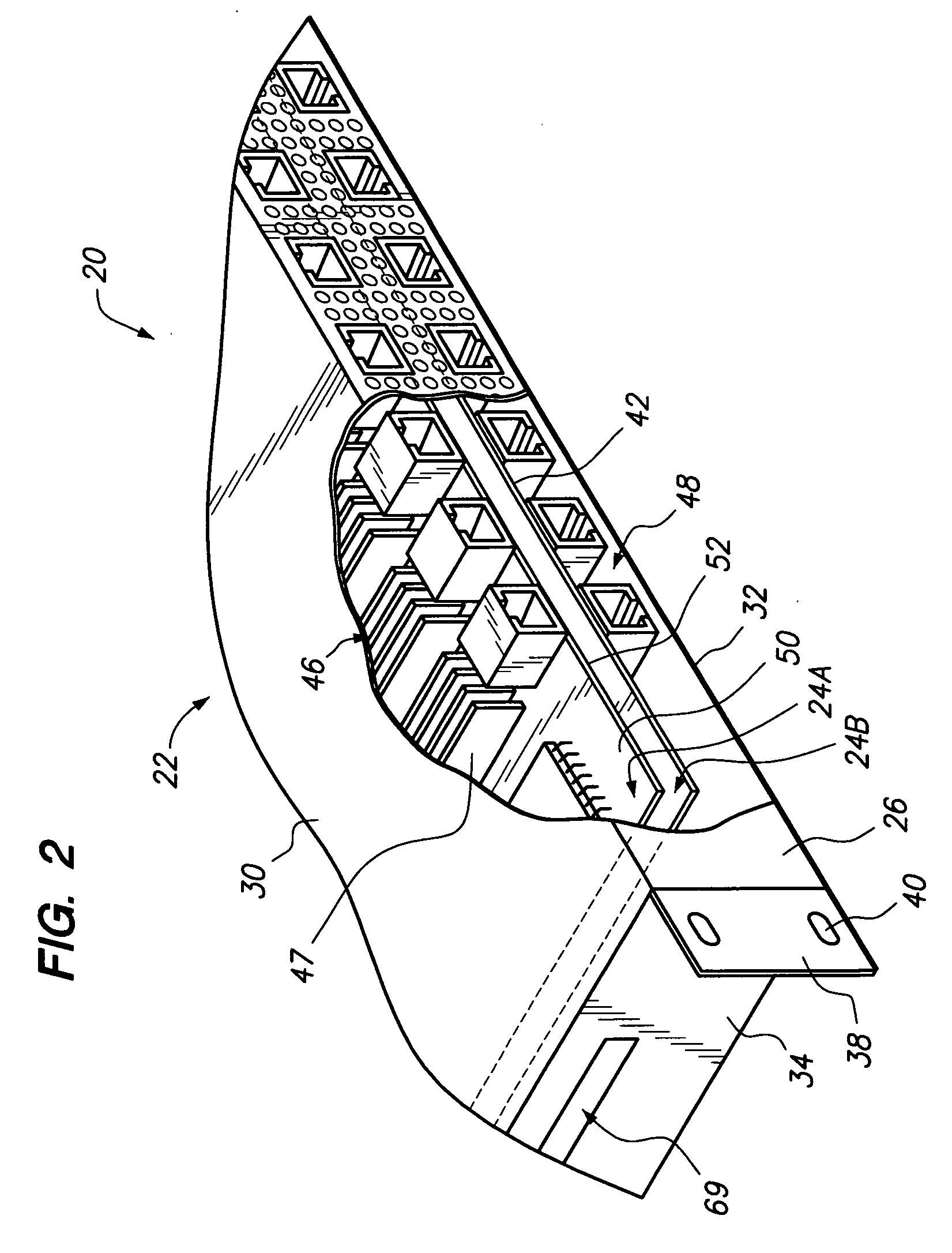
[0022]One embodiment of the invention is a configuration of a chassis including one or more communication boards. One aspect of the invention is a cooling configuration for the boards. Yet another aspect of the invention is a configuration of data ports of the boards.

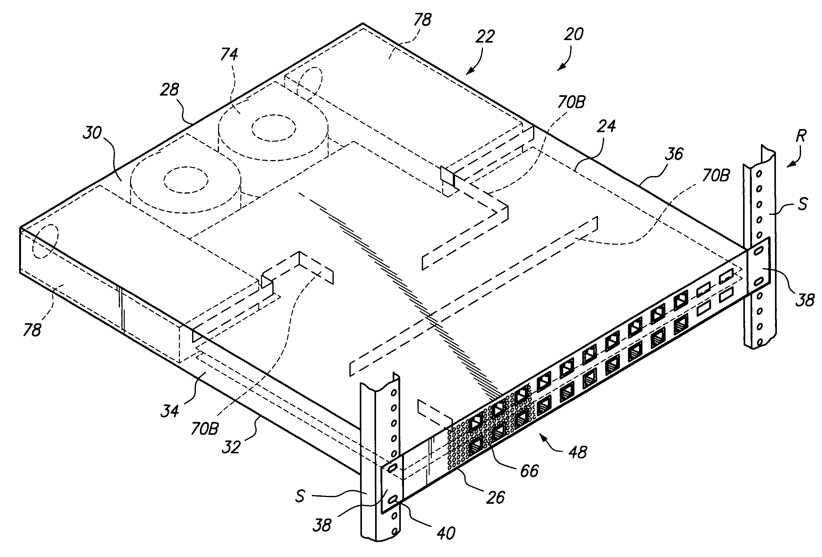
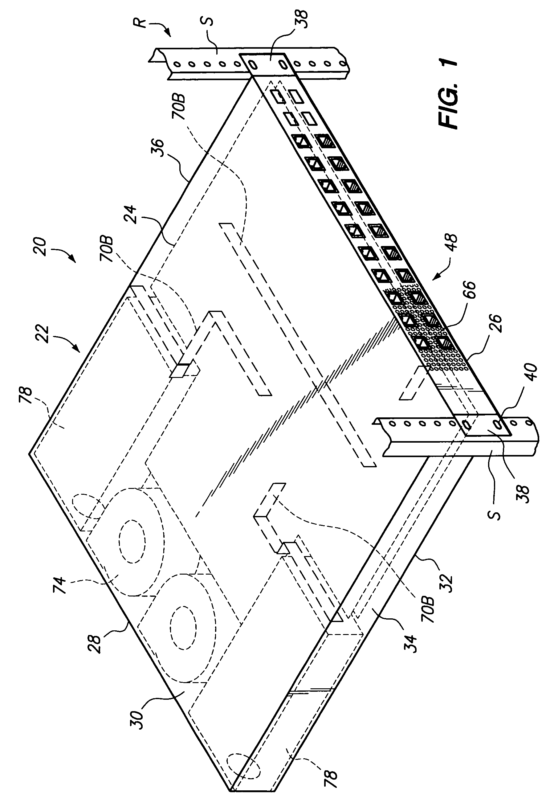
[0023]FIG. 1 illustrates a chassis 20 in accordance with one embodiment of the present invention. The chassis 20 comprises a housing 22 and one or more boards 24.

[0024]In one embodiment, the housing 22 comprises an enclosure for the one or more boards 24. As illustrated, the housing 22 has a front 26, a rear 28, a top 30, a bottom 32, ...


PUM


Abstract

A cooling configuration is provided for chassis-mounted electronics boards. In one embodiment, the chassis comprises a housing and at least two electronics boards. The electronics boards may comprise communication boards having a plurality of ports. Cooling air spaces are defined above and below each board, permitting cooling air to be drawn over both sides of each board. Baffles may be provided at both sides of the boards for controlling the flow of air through the various air spaces, such as baffles extending down from a top of the housing or up from a bottom of the housing, or baffles located between the boards.

Description

FIELD OF THE INVENTION[0001]The present invention relates to configurations for circuit boards, housings, and in particular for configurations for cooling and efficient space utilization for circuit boards and housings.BACKGROUND OF THE INVENTION[0002]Various electronic equipment is utilized to provide data connections between components and to process data. This equipment may comprise a communication board having a substrate bearing a number of connectors, data processing components (filters, converters, processors and the like) and associated connecting circuitry. The connectors may be of a variety of types and permit cable connection to the board.[0003]These communication boards may be mounted in a housing or chassis for protection and support. Unfortunately, this same mounting increases the likelihood of overheating of the board and makes the various components of the board, including the connectors, less accessible. In addition, in many situations, these chassis are mounted in ...

Claims


Application Information

Patent Timeline
IPC IPC(8): H05K7/20
CPCH05K7/20727
Inventor MUSCIANO, MICHAEL JOSEPHDANIELS, DOUGLAS RONALDBARABI, NASSER
Owner MARVELL INT LTD
Learn More