Variable speed tool and variable speed control method

a variable speed and control method technology, applied in the field can solve the problems of unfavorable manual operation of operators, and achieve the effects of stable operation, and stable operation of variable speed tools

Active Publication Date: 2009-11-12
POSITEC POWER TOOLS (SUZHOU) CO LTD
View PDF29 Cites 31 Cited by
  • Summary
  • Abstract
  • Description
  • Claims
  • Application Information

AI Technical Summary

Benefits of technology

[0006]Another technical problem to be solved by the present invention is to provide a variable speed tool, which can stably work in a state of high output rotating speed and the low torque.
[0007]Another technical problem to be solved by the present invention is to provide a variable speed tool, which can stably work in a state of low output rotating speed and the high torque.
[0015]The variable speed tool of the present invention uses the feature that a first planetary gear set drives the rotation of a first inner toothed ring when a load torque increases and forms the sliding groove in the outer circumferential surface of the first inner toothed ring (namely the torque sensing ring) with the gearshift ring coupled to the gearshift fork of which the guiding portion is movably received in the sliding groove and the gearshift fork made axially moveable under the action of a first spring member so as to cause the gearshift ring to axially move and change the engagement relationship thereof with the multistage transmitting gear train, thereby realizing automatic adjustment of the rotating speed and the output torque of the outputting shaft.

Problems solved by technology

However, such a manual operation requires the operator to constantly watch the operation condition and variation of load of the tool for determining the timing for adjusting the speed changing mechanism.
Such a manual operation is not friendly to the operator.

Method used


Image

  • Variable speed tool and variable speed control method
  • Variable speed tool and variable speed control method
  • Variable speed tool and variable speed control method

Examples


Embodiment Construction

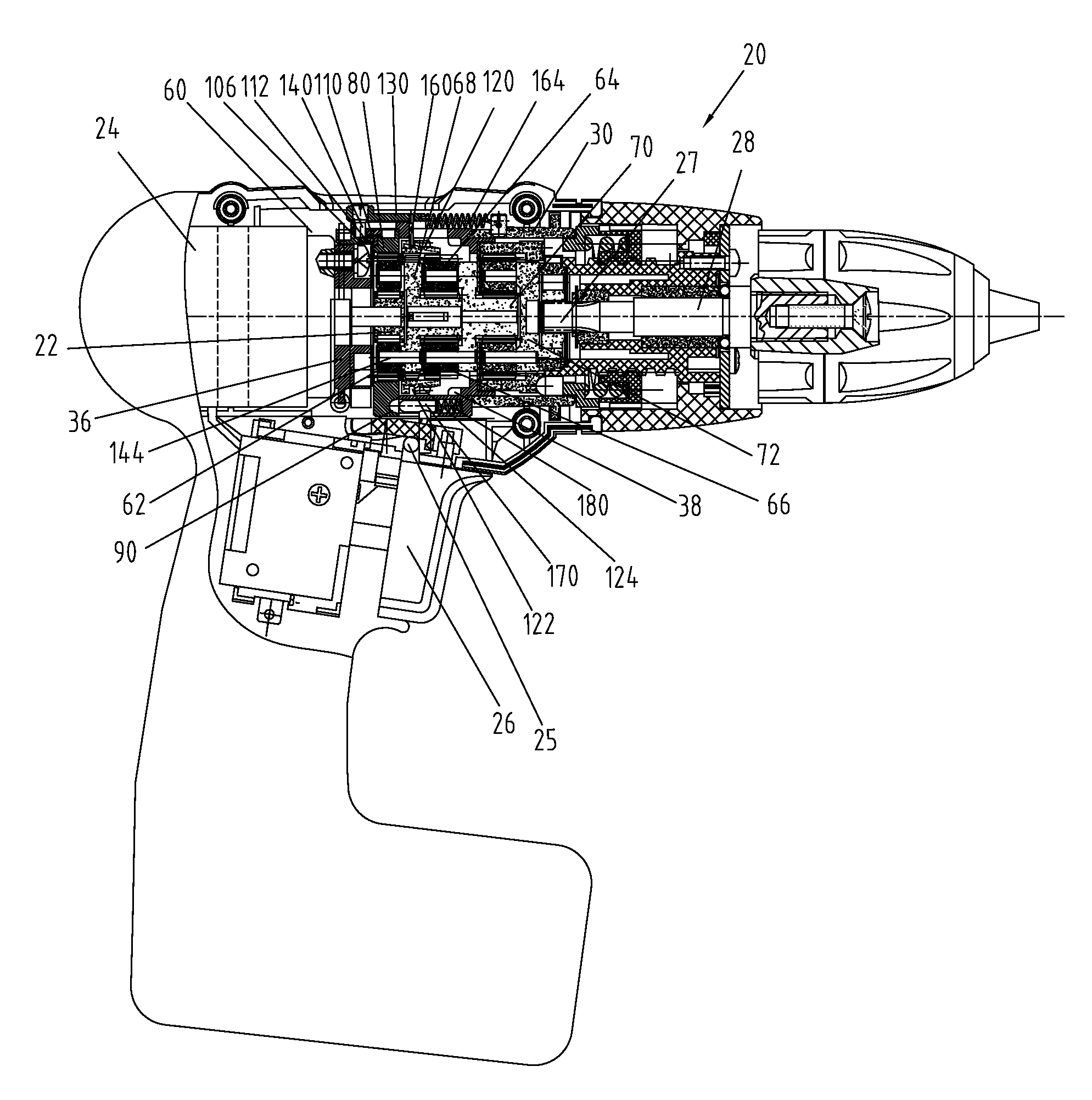
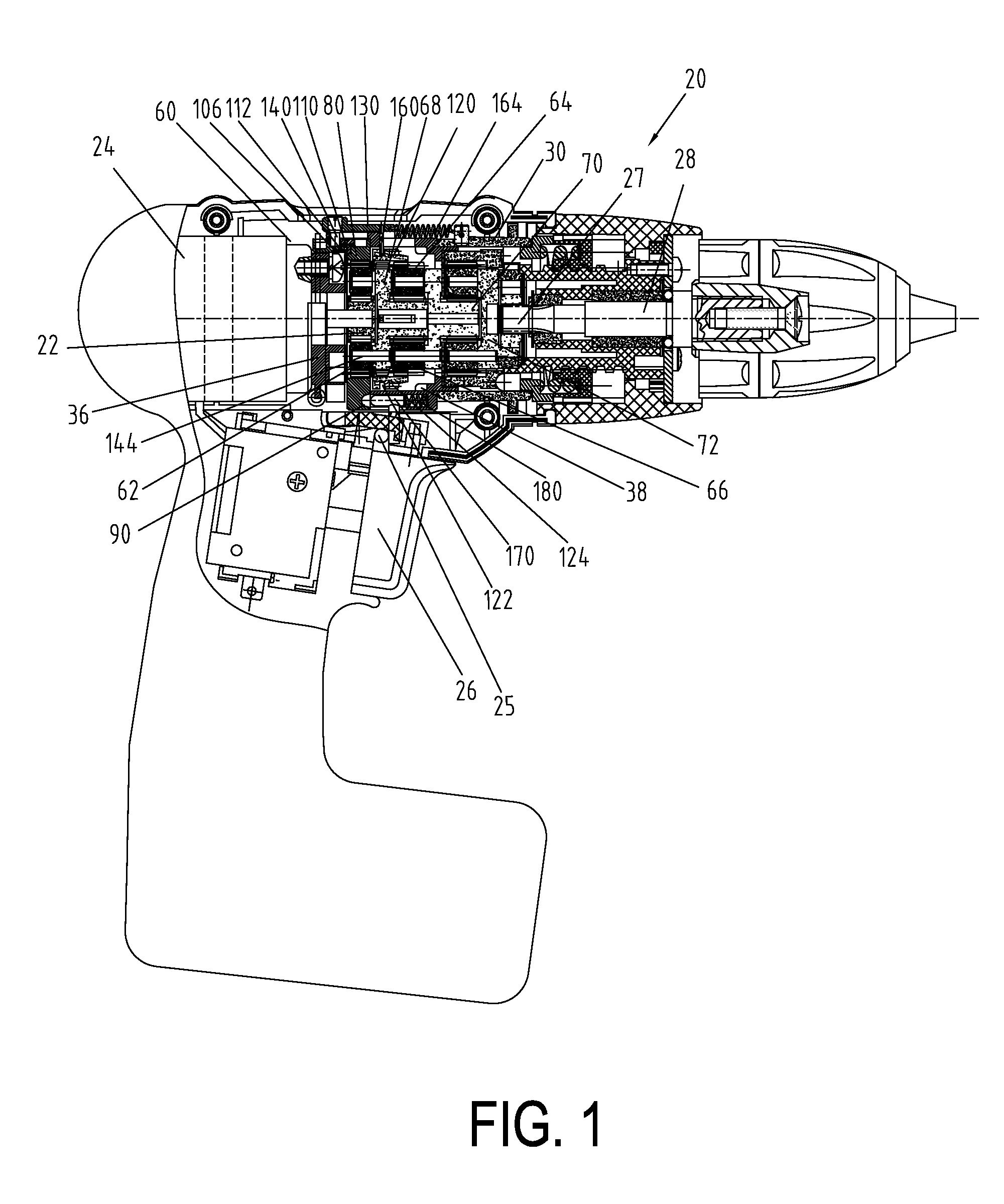
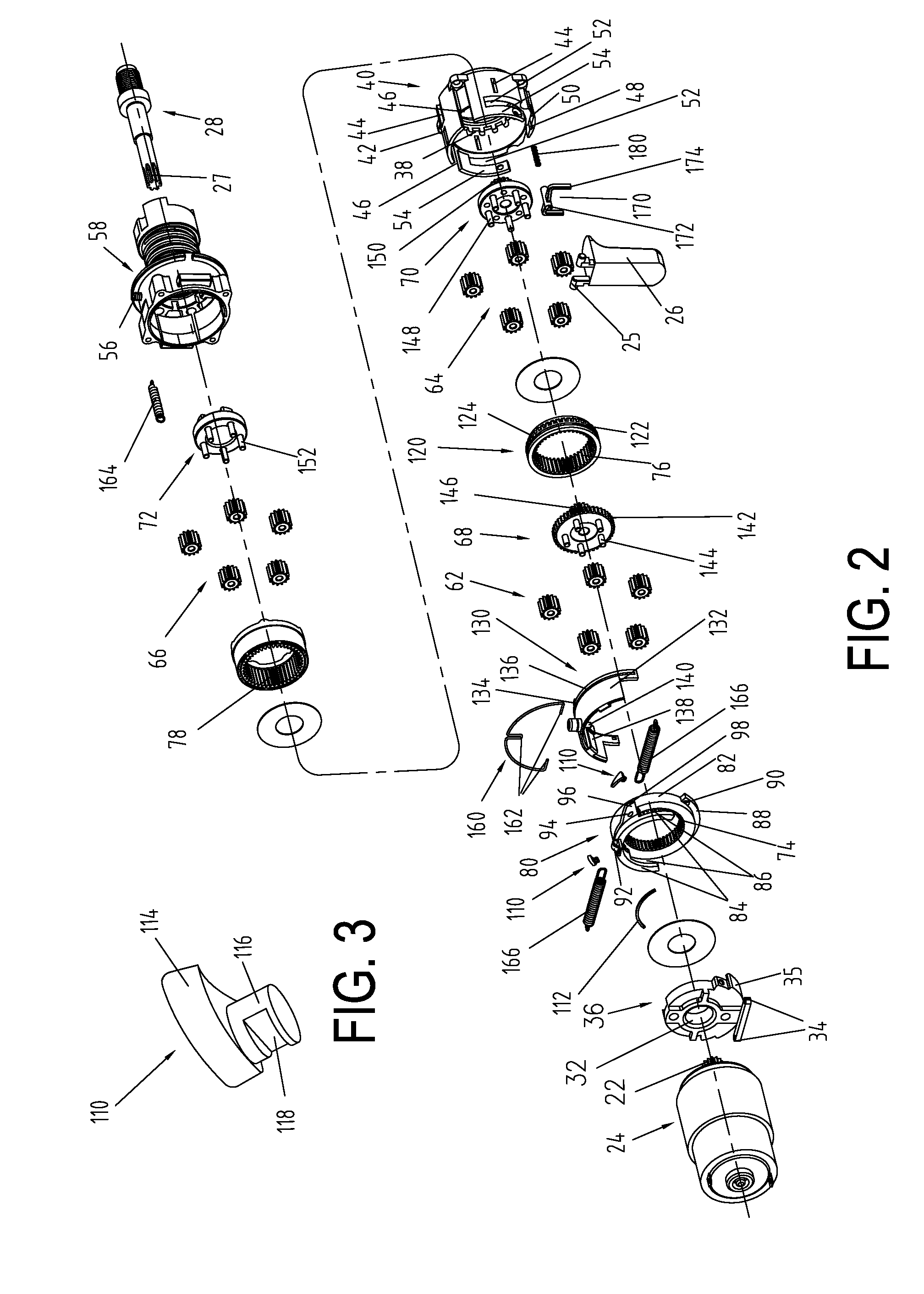
[0040]An electric drill 20 will be taken as an example to describe a preferred embodiment of the present invention, more particularly a gearshift device realizing an axial movement of a gearshift ring and a gear-shifting method thereof.

[0041]Referring to FIGS. 1-5, the electric drill 20 comprises a motor 24 having a motor shaft 22, a switch having two brackets 25 and functioning to start / stop the motor 24, an outputting shaft 28 having an outer toothed ring 27, a gearbox housing 30, a multistage transmitting gear train 60 connecting the motor shaft 22 and the outputting shaft 28, a torque sensing ring 80 driven by the multistage transmitting gear train 60 for rotation, an axially movable gearshift ring 120 coupled to the multistage transmitting gear train 60, a gearshift fork 130, a C-shaped metal ring 160 having three supporting feet 162, a tension spring 164 arranged between the gearbox housing 30 and the gearshift fork 130, two tension springs 164 arranged between the torque sens...


PUM

PropertyMeasurementUnit
Forceaaaaaaaaaa
Angleaaaaaaaaaa
Speedaaaaaaaaaa

Abstract

The present invention has disclosed a variable speed tool and a variable speed control method. The tool includes a switch; a gearbox housing; a motor; an outputting shaft; a multistage transmitting gear train and a gearshift ring which are mated with the motor and the outputting shaft, the gearshift ring having inner teeth; a gearshift fork mated with the gearshift ring; a tension spring arranged between the gearbox housing and the gearshift fork; and a torque sensing ring provided with a sliding groove in which the gearshift fork is movably disposed. When the load of the outputting shaft has reached to a predetermined value, the torque sensing ring makes the gearshift fork move axially in the sliding groove under the action of the tension spring, thus bringing the gearshift ring to move axially. The variable speed tool of the present invention may automatically adjust the rotating speed and the torque of the outputting shaft according to a variation of the load torque.

Description

BACKGROUND OF THE INVENTION[0001]1. Field of the Invention[0002]The present invention relates to a variable speed tool, and more particularly to a tool, such as an electric drill, a screw driver, and a hammer drill, which has a multistage variable speed transmitting mechanism for outputting various rotational speeds as being driven by an electric motor, a pneumatic motor, or a hydraulic motor and a variable speed control method for controlling the variable speed tool.[0003]2. Description of the Prior Art[0004]A variable speed tool, such as an electric drill, a screw driver, and a hammer drill, has a multistage variable speed transmitting mechanism that may output various rotating speeds according to a variation of the load torque. The multistage variable speed transmitting mechanism of the variable speed tool typically comprises a multistage transmitting gear train and a gearshift device, which are coupled between a motor and an outputting shaft. An axial movement of the gearshift d...

Claims


Application Information

Patent Timeline
IPC IPC(8): B23B47/14F16H3/44F16H3/74B23Q15/08B23B45/02
CPCB23B45/008B25F5/001B25B23/141B25B21/008
Inventor CHEN, CHENGZHONG
Owner POSITEC POWER TOOLS (SUZHOU) CO LTD
Why Eureka
Try Eureka