Electrooptic apparatus substrate and examining method therefor and electrooptic apparatus and electronic equipment
a technology of electrooptic apparatus and substrate, which is applied in the direction of instruments, measurement devices, computing, etc., can solve the problems of increasing the time taken for feeding back the method of examining a finished product is not preferable from the viewpoint of management of manufacturing steps, and the delay in the detection of a poor product, etc., to achieve satisfactory measurement accuracy
- Summary
- Abstract
- Description
- Claims
- Application Information
AI Technical Summary
Benefits of technology
Problems solved by technology
Method used
Image
Examples
first embodiment
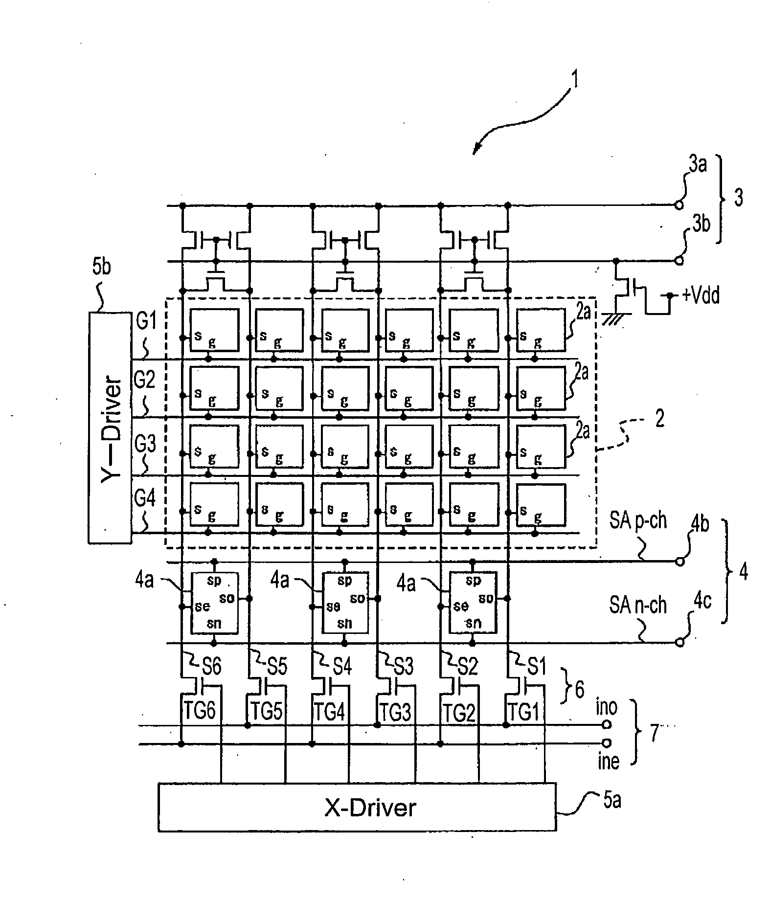
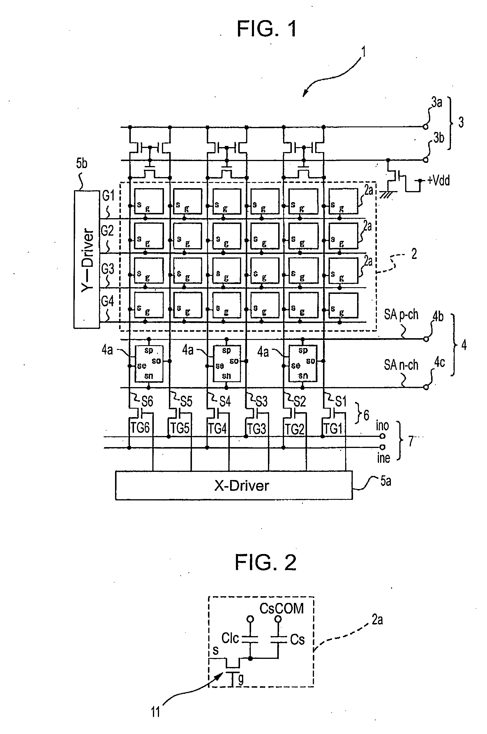
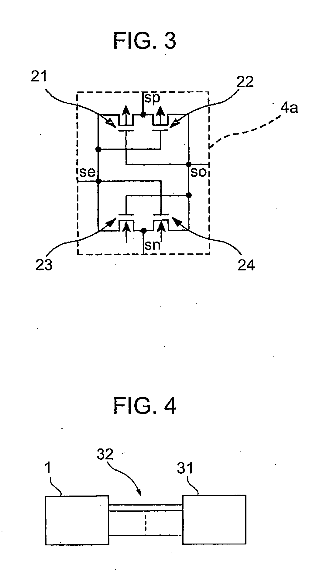
[0090]First of all, FIG. 1 is a circuit diagram of an element substrate of a liquid crystal display device according to a first embodiment of the invention. The element substrate of the liquid crystal display device is an active-matrix type display device substrate. An element substrate 1 includes a display element array portion 2, a pre-charge circuit portion 3 and a display data reading circuit portion 4. The display element array portion 2 serving as a display portion includes multiple pixel cells in a two-dimensional m×n matrix. Here, m and n are both integers. An X-driver portion 5a, a Y-driver portion 5b, a transmission gate portion 6, and an image signal line 7 are further included therein in order to drive multiple pixels 2a aligned in the X-direction (horizontal direction) and Y-direction (vertical direction, of the display element array portion 2. The X-driver portion 5a, Y-driver portion 5b, transmission gate portion 6 and image signal line 7 serve as a data writing unit ...
second embodiment
[0162]Next, a second embodiment of the present invention will be described. FIG. 12 is a circuit diagram of an element substrate of a liquid crystal display device according to the second embodiment of the present invention. In FIG. 12, the same reference numerals are given to the same components as those of the first embodiment, and the description thereof will be omitted herein.
[0163]An element substrate 1B of the liquid crystal display device according to this embodiment also includes the display element array portion 2, the display data reading circuit portion 4, the X-driver portion 5a, the Y-driver portion 5b (not shown in FIG. 12) the transmission gate portion 6, the image signal line 7, and the differential amplifier 10. According to this embodiment, the element substrate 1B further includes a pre-charge circuit portion 13, a connection gate portion 14 and a reference voltage supplying portion 15.
[0164]The pre-charge circuit portion 13 of the second embodiment has a transist...
third embodiment
[0198]Next, a third embodiment of the present invention will be described. FIG. 15 is a circuit diagram of an element substrate of a liquid crystal display device according to the third embodiment of the present invention. In FIG. 15, the same reference numerals are given to the same components as those of the first embodiment, and the description thereof will be omitted herein.
[0199]An element substrate 1C of the liquid crystal display device according to this embodiment also includes the display element array portion 2, the display data reading circuit portion 4, the X-driver portion 5a, the Y-driver portion 5b knot shown in FIG. 15), the transmission gate portion 6, the image signal line 7, and the differential amplifier 10. According to this embodiment, the element substrate 1C further includes a pre-charge circuit portion 16, a connection gate portion 17 and a reference voltage supplying portion 18.
[0200]The pre-charge circuit portion 16 of the third embodiment has a pair of tr...
PUM
 Abstract
Description
Claims
Application Information
 - Generate Ideas
- Intellectual Property
- Life Sciences
- Materials
- Tech Scout
- Unparalleled Data Quality
- Higher Quality Content
- 60% Fewer Hallucinations
Browse by: Latest US Patents, China's latest patents, Technical Efficacy Thesaurus, Application Domain, Technology Topic, Popular Technical Reports.
© 2025 PatSnap. All rights reserved.Legal|Privacy policy|Modern Slavery Act Transparency Statement|Sitemap|About US| Contact US: help@patsnap.com


