
Apparatus, system, and method for skin tone detection in a CMOS image sensor

a technology of image sensor and skin tone, applied in the field of skin tone detection techniques, can solve the problems of skin tone detection accuracy dependent on lighting, requires more computing power than desired, and based on optimal solution image processing algorithms typically require substantial computational resources,

Active Publication Date: 2009-10-22
OMNIVISION TECH INC
View PDF0 Cites 37 Cited by
  • Summary
  • Abstract
  • Description
  • Claims
  • Application Information

AI Technical Summary

Benefits of technology

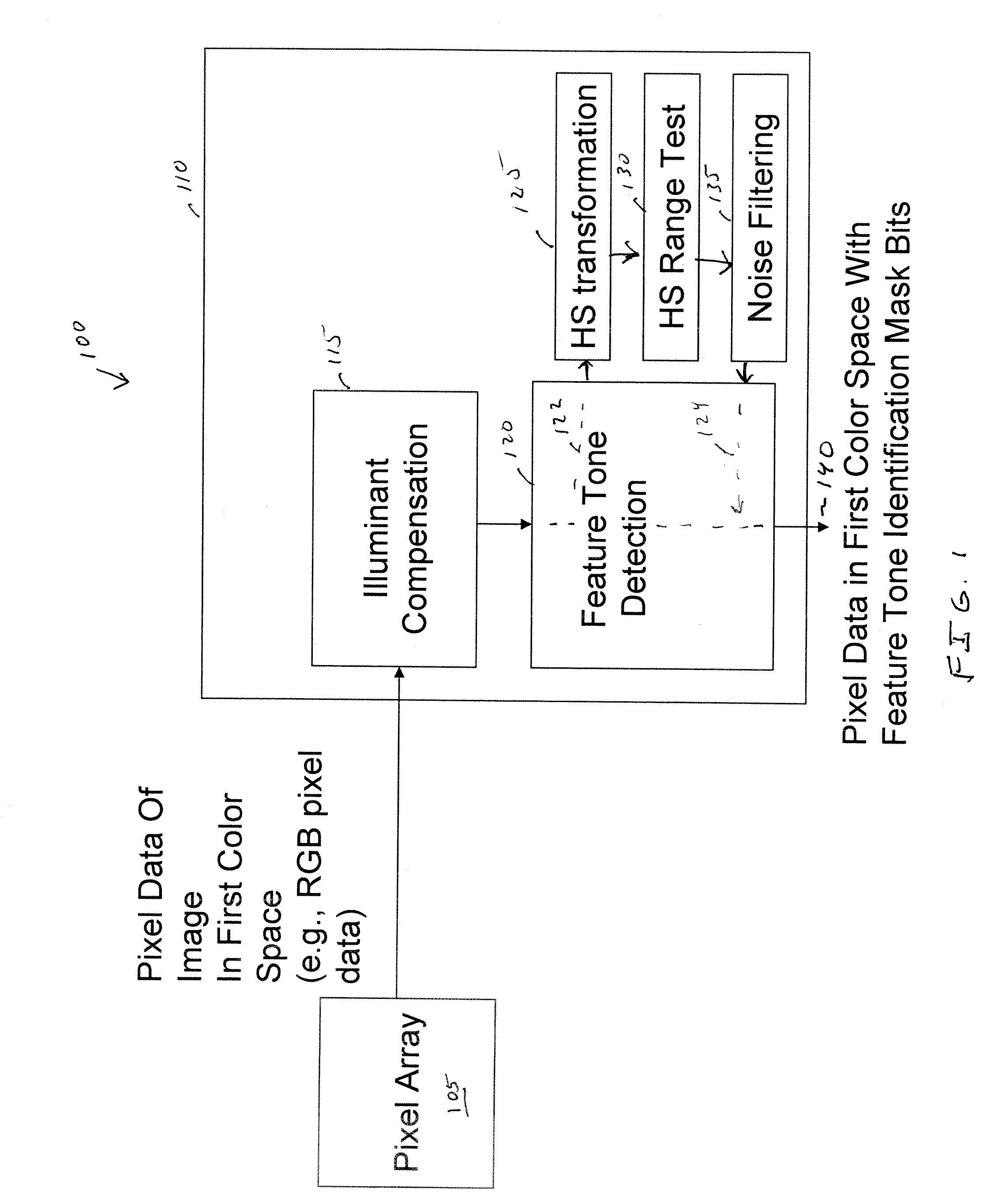
[0007]One embodiment of the invention is a method of detecting feature tones using pixel data generated by a Complementary Metal Oxide Semiconductor (CMOS) image sensing system. The CMOS image sensing system receives illumination compensated pixel data of a captured image in a first color space. Feature tone detection is then performed on a copy of the illumination compensated pixel data. The copy of the illumination compensated pixel data is transformed to a second color space that includes hue and saturation. Each pixel of the

Problems solved by technology

However, these approaches based on optimal solution image processing algorithms typically require substantial computational resources and are too expensive to be integrated into high-volume consumer products.
However, the conventional approach to achieving an integrated skin tone detection capability in a CMOS image sensor has several drawbacks.
One problem with UV based skin detection approaches is that it still requires more computing power than desired, due to the need to perform mathematical division operations to transform the RGB space into the UV space.
Another problem is that performing skin tone detection in a UV space may make the skin tone detection accuracy dependent on lighting conditions.
That is, when the same skin surface is lit with different illuminants the UV components of the captured image will vary, which in turn may cause errors in the skin tone detection algorithm.
This is exacerbated by the problems in the prior art in implementing a low-cost noise filtering to eliminate false skin detection.

Method used


Image

  • Apparatus, system, and method for skin tone detection in a CMOS image sensor
  • Apparatus, system, and method for skin tone detection in a CMOS image sensor
  • Apparatus, system, and method for skin tone detection in a CMOS image sensor

Examples


Embodiment Construction

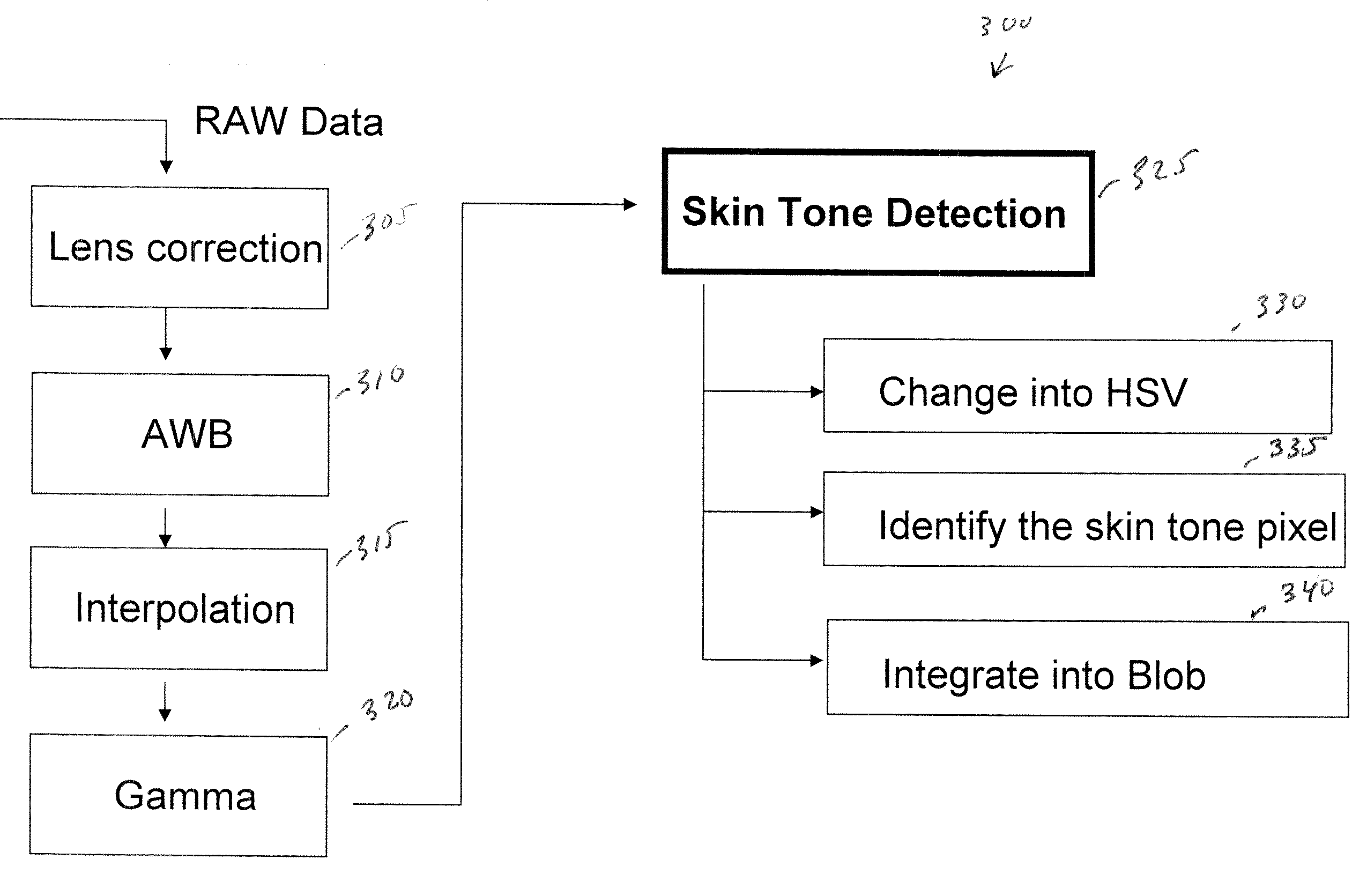
[0015]FIG. 1 is a block diagram of an imaging system 100 in accordance with one embodiment of the present invention. A pixel array 105 generates pixel data in a first color space. As one example, the pixel data may be Red-Green-Blue (RGB) pixel data having a pre-selected number of bits allocated for each pixel to represent color data in each color channel (e.g., 8 bits per color in one implementation). However, it will be understood throughout the following discussion that RGB is merely an exemplary first color space and that other known alternatives to RGB are contemplated.

[0016]A captured digital image may be read out from pixel array 105 using conventional techniques, such as a row-by-row line readout. An image processing portion 110 processes the pixel data of a captured image and may include a line buffer memory (not shown) to buffer pixel data for a pre-selected number of lines of pixel data. Image processing portion 110 may be implemented using dedicated hardware and / or softw...


PUM


Abstract

An image sensing system provide feature tone detection. A feature tone detection module receives illumination compensated pixel data. To perform feature tone identification the illumination compensated pixel data is transformed to a color space having hue and saturation and then compared against pre-selected ranges of hue and saturation. Noise filtering is performed using an erosion-dilation process. A bit code is used to identify pixels having a specified feature tone, such as a skin tone.

Description

FIELD OF THE INVENTION[0001]The present invention is generally related to skin tone detection techniques. More particularly, the present invention is directed towards skin tone detection techniques in CMOS image sensors.BACKGROUND OF THE INVENTION[0002]There is increasing interest in the detection of human skin tones in digital images. Skin tone detection may be used, for example, to assist in facial detection and body detection. In the prior art various skin tone detection techniques have been implemented using expensive Digital Signal Processors (DSPs) or computers to identify skin tones in digital images using complicated optimal solution mathematical algorithms to identify skin tones and perform various image analysis processes. However, these approaches based on optimal solution image processing algorithms typically require substantial computational resources and are too expensive to be integrated into high-volume consumer products.[0003]There is interest in implementing skin t...

Claims


Application Information

Patent Timeline
IPC IPC(8): G06K9/34G06V10/56
CPCG06K9/4652G06V10/56
Inventor XIONG, WEIHUASHAN, JIZHANG
Owner OMNIVISION TECH INC
Learn More