Portable Electronic Device and Light Flickering Method for Light Emitting Element Thereof

a technology of electronic devices and light flickering, applied in the direction of electric variable regulation, process and machine control, instruments, etc., can solve the problems of inability to modify users and predetermined emission of diodes

Active Publication Date: 2009-10-22
HTC CORP
View PDF7 Cites 15 Cited by
  • Summary
  • Abstract
  • Description
  • Claims
  • Application Information

AI Technical Summary

Benefits of technology

[0009]In one embodiment of the invention, the portable electronic device includes at least one light emitting element, a user interface, a storage unit, a first processing unit, and a driving signal generator. The user interface is configured to set personalized light flickering data, and the storage unit stores the personalized light flickering data. Moreover, the first processing unit generates a control signal in accordance with the personalized light flickering data stored in the storage unit, and the driving signal generator generates at least one driving signal in accordance with the control signal

Problems solved by technology

The flickering mode of the light emitting diodes is predetermined and cannot be modified by a user.

Method used


Image

  • Portable Electronic Device and Light Flickering Method for Light Emitting Element Thereof
  • Portable Electronic Device and Light Flickering Method for Light Emitting Element Thereof
  • Portable Electronic Device and Light Flickering Method for Light Emitting Element Thereof

Examples


first embodiment

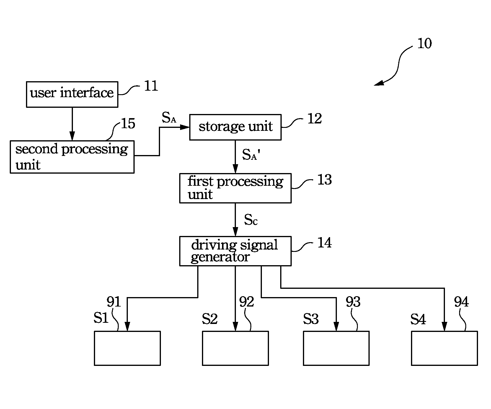
[0028]FIG. 1 is a functional block diagram of a portable electronic device according to the invention. With reference to FIG. 1, the mobile phone 10 includes light emitting diodes 91˜94, whose flickering mode can be adjusted by users. In addition, the mobile phone 10 also includes a user interface 11, a storage unit 12, a first processing unit 13, a driving signal generator 14, and a second processing unit 15. The users of the mobile phone may input personalized light flickering data SA, and the second processing unit 15 then transmits the personalized light flickering data SA into the storage unit 12 for storing the personalized light flickering data SA. The first processing unit 13 may generate a control signal SC in accordance with the personalized light flickering data SA′ outputted by the storage unit 12, and thus the driving signal generator 14 may generate driving signals S1˜S4, in accordance with the control signal SC, to the light emitting diodes 91˜94 so as to respectively...

second embodiment

[0035]On the other hand, FIG. 3 is a functional block diagram of a portable electronic device according to the invention. With reference to FIG. 3, the mobile phone 30 may include a light sensor 36, which detects ambient light outside the electronic device and outputs a light sensing signal SL, and then the first processing unit 33 will adjust the control signal SC in accordance with the light sensing signal SL and the driving signal generator 34 generates the driving signals S1˜S4 to control the brightness of the light emitting diodes 91˜94.

[0036]The aforesaid condition is illustrated in the FIG. 4, which is a schematic graph illustrating the relation between the ambient light luminance and the brightness ratio of light emitting diodes according to the second embodiment of the invention. For example, the mobile phone is operated in a first brightness mode, a second brightness mode, and a third brightness mode, respectively corresponding to brightness ratios Y1%, Y2% and Y3% (from l...


PUM


Abstract

A portable electronic device and a light flickering method for light emitting elements thereof are both disclosed herein. The portable electronic device includes at least one light emitting element. The light flickering method comprises the following steps: setting personalized light flickering data with a user interface; storing the personalized light flickering data; generating a control signal in accordance with the personalized light flickering data; and generating a driving signal in accordance with the control signal and driving the light emitting elements with the driving signal.

Description

RELATED APPLICATIONS[0001]This application claims priority to Taiwan Application Serial Number 97114689, filed Apr. 22, 2008, which is herein incorporated by reference.BACKGROUND[0002]1. Field of Invention[0003]The invention relates to an electronic device, more particularly, to a portable electronic device.[0004]2. Description of Related Art[0005]Portable electronic devices such as mobile phones, personal digital assistants, notebooks etc., are currently very advanced and integrating new functions into portable electronic devices is one of the trends for designing these devices. However, since the importance of a friendly user experience for portable electronic devices has been aware of by device designers, it becomes an attractive design for portable electronic devices to allow a user to adjust a variety of settings thereof so as to comply with the user's demands.[0006]Take light emitting diodes disposed within the portable electronic device for example. The flickering mode of the...

Claims


Application Information

Patent Timeline
IPC IPC(8): H05B37/02H05B44/00
CPCH04M1/22H05B37/029H05B33/0803H05B47/155H05B45/325
Inventor YANG, MING-JER
Owner HTC CORP
Why Eureka
Try Eureka