
Grates with heat shield

Active Publication Date: 2009-10-22
ELECTROLUX HOME PROD CORP NV
View PDF31 Cites 6 Cited by
  • Summary
  • Abstract
  • Description
  • Claims
  • Application Information

AI Technical Summary

Benefits of technology

[0003]The following presents a simplified summary of the invention in order to provide a basic understanding of some example aspects of the invention. This summary is not an extensive overview of the invention. Moreover, this summary is not intended to

Problems solved by technology

However, because of the open geometry, a great deal of excess radiant heat from the burners leaks out around each of the sides of the grates.
The radiant heat can cause excessive heat issues such as around a control panel that includes control knobs.
The radiant heat can also cause excessive heat issues at other areas surrounding the heating elements.

Method used


Image

  • Grates with heat shield
  • Grates with heat shield
  • Grates with heat shield

Examples


Embodiment Construction

[0015]Example embodiments that incorporate one or more aspects of the present invention are described and illustrated in the drawings. These illustrated examples are not intended to be a limitation on the present invention. For example, one or more aspects of the present invention can be utilized in other embodiments and even other types of devices. Moreover, certain terminology is used herein for convenience only and is not to be taken as a limitation on the present invention. Still further, in the drawings, the same reference numerals are employed for designating the same elements.

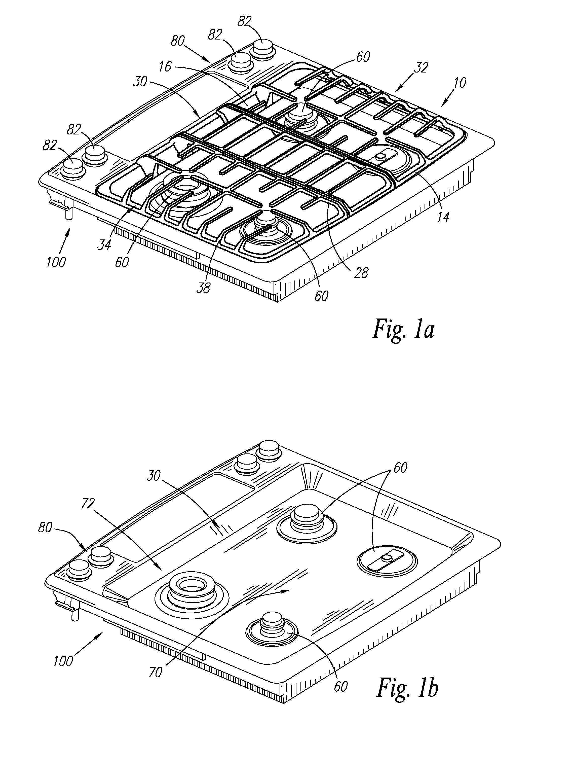
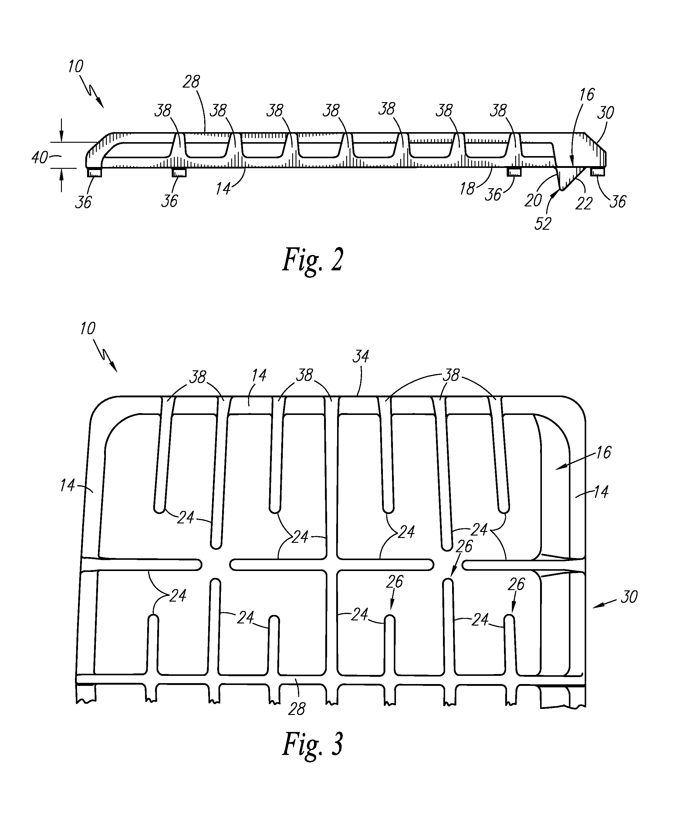
[0016]Turning to the shown example of FIGS. 1-5, the subject invention relates to a grate 10 for use with a cooking apparatus 100, such as a range. As seen in FIG. 1A, the cooking apparatus 100 includes at least one heat source 60. The heat source 60 can be a burner, such as a gas burner, or any other suitable heating apparatus. The at least one heat source 60 can be located at various locations througho...


PUM


Abstract

In accordance with one aspect of the present invention, a cooking apparatus is provided. The cooking apparatus comprises a cooking surface, at least one grate, and a guard. The cooking surface includes at least one heat source and a control panel. The at least one grate is provided over a portion of the cooking surface. The guard is coupled to the at least one grate. The guard includes a first side and a second side. The first side of the guard is configured to deflect heat radiating from the at least one heat source. The second side of the guard corresponds with a sidewall of the cooking surface to form a channel between the guard and the sidewall. The channel is configured to create a thermal barrier between the at least one heat source and the control panel.

Description

FIELD OF THE INVENTION[0001]The present invention relates generally to grates for use with cooking apparatuses, and more particularly, to grates that support cooking implements or containers where the grates include at least one guard to prevent radiant heat from reaching a control panel.BACKGROUND OF THE INVENTION[0002]Typically, a cooking apparatus such as a range includes grates that are used to support a pot or pan, over the heat provided from a heating source, such as a gas burner. Conventionally, the grates are located directly over the gas burners and have a generally open geometry featuring a cooking support surface formed of a plurality of support members for supporting the cooking implement. However, because of the open geometry, a great deal of excess radiant heat from the burners leaks out around each of the sides of the grates. The radiant heat can cause excessive heat issues such as around a control panel that includes control knobs. The radiant heat can also cause exc...

Claims


Application Information

Patent Timeline
IPC IPC(8): F24C15/36F24C15/10F24C15/00F23H17/00
CPCF24C15/107F24C15/006
Inventor SCOTT, TIMOTHY D.CLARK, ADAMBRANT, RONALD G.HAUPT, DAVID JOSEPHSHEAVES, BRUCE GERALD
Owner ELECTROLUX HOME PROD CORP NV
Learn More