
Video server, video client device and video processing method thereof

a video server and video client technology, applied in the field of video systems, can solve the problems of not being able to have their photo taken together, time-consuming, complicated,

Inactive Publication Date: 2009-10-15
HONG FU JIN PRECISION IND (SHENZHEN) CO LTD +1
View PDF13 Cites 43 Cited by
  • Summary
  • Abstract
  • Description
  • Claims
  • Application Information

AI Technical Summary

Benefits of technology

[0002]Embodiments of the present disclosure relate to video systems, and particularly to a video system including a video server, at least two video clients, and a video processing method of the video system.

Problems solved by technology

However, graphics editing software, such as Adobe Photoshop®, can be used to create a photo collage to simulate a group photo, but it is complicated and time consuming.
However, the two users may want to have a group photo but because they are spatially apart they may not be able to have their photo taken together.

Method used


Image

  • Video server, video client device and video processing method thereof
  • Video server, video client device and video processing method thereof
  • Video server, video client device and video processing method thereof

Examples


second embodiment

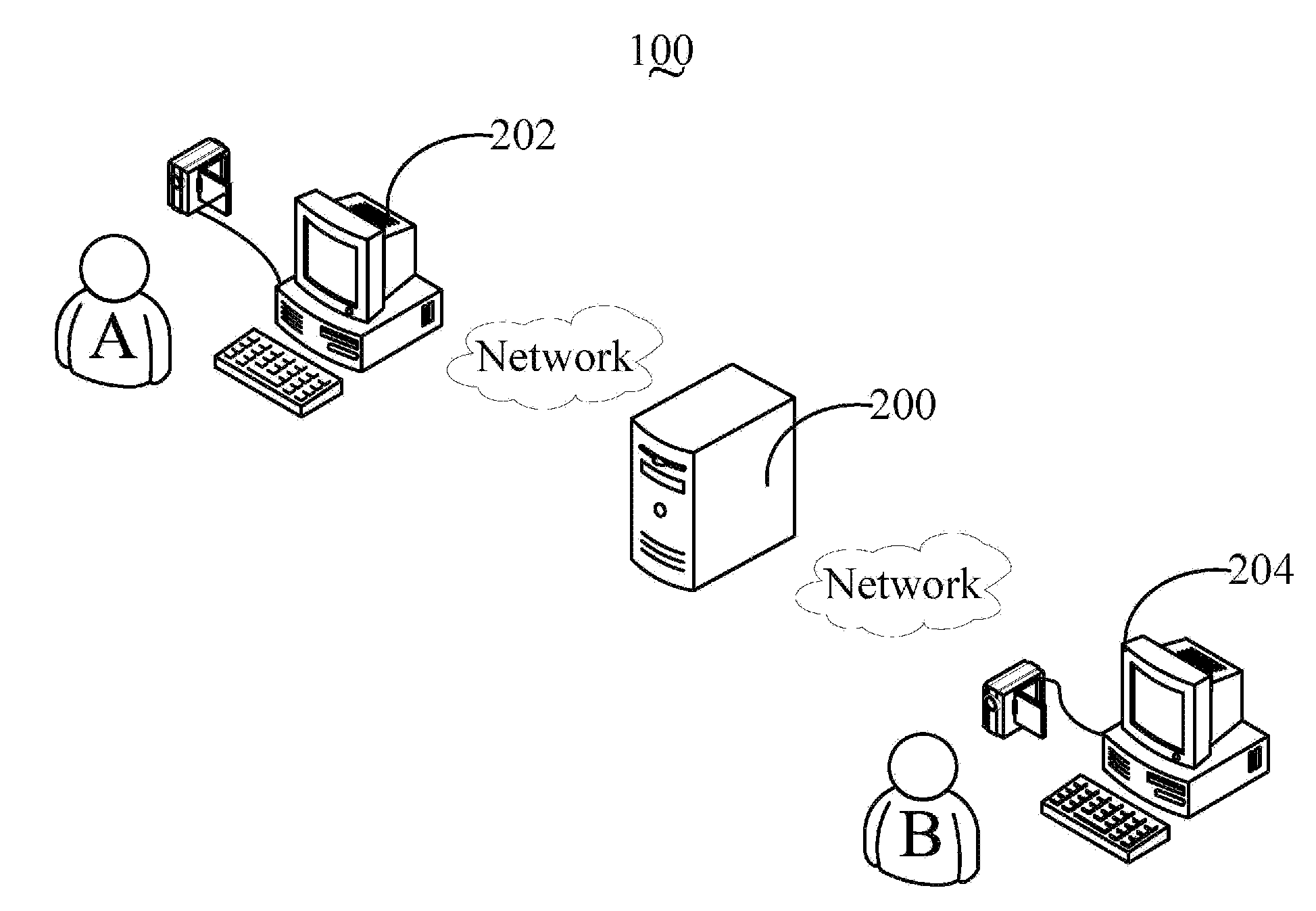
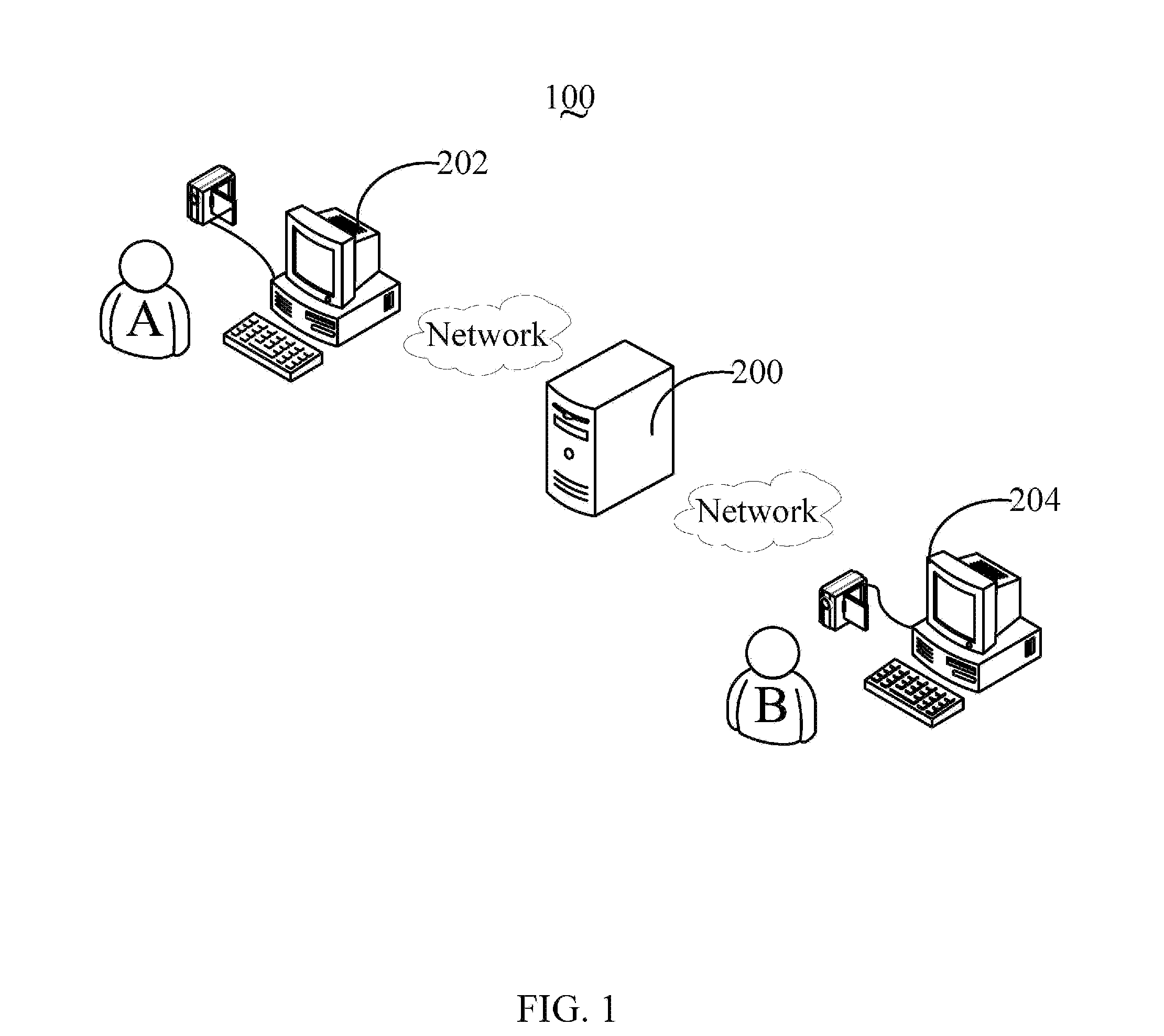
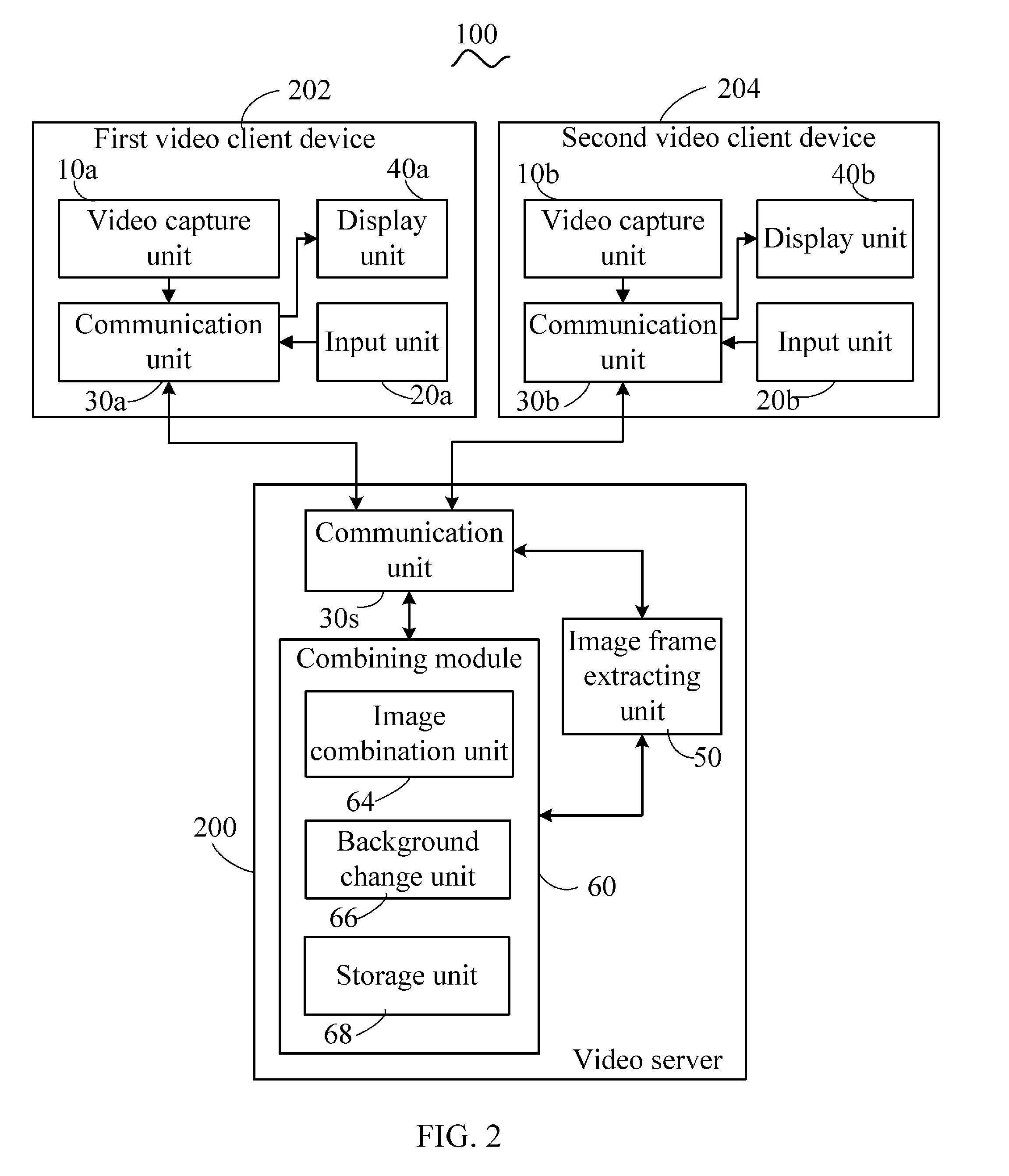
[0034]In other conditions, the combining module 60 and the image frame extracting unit 50 may be disposed in one of the first and second video client devices 202, 204. For example, referring to FIG. 5, a video system 300 in accordance with a second embodiment is illustrated. The video system 300 includes a video server 205, a first video client device 206, and the second video client device 204. When compared with the video server 200, the video server 205 is only used for transmitting information between the first and second video client devices 206, 204. When compared with the first video client device 202, the first video client device 206 includes a combining module 60a and an image frame extracting unit 50a, functions of which are similar to the combining module 60 and the image frame extracting unit 50 of FIG. 2. The combining module 60a includes an image combination unit 64a, a background change unit 66a, and a storage unit 68a, functions of which are similar to the image com...

third embodiment

[0036]Understandably, the combining module 60 and the image frame extracting unit 50 may be disposed in both the first and second video client devices 202, 204. For example, referring to FIG. 6, a video system 400 in accordance with a third embodiment is illustrated. The video system 400 includes the video server 205, the first video client device 206, and a second video client device 207. When compared with the video system 300 of FIG. 5, the second video client device 207 includes a combining module 60b and an image frame extracting unit 50b, functions of which are similar to the combining module 60a and the image frame extracting unit 50a of FIG. 5. The combining module 60b includes an image combination unit 64b, a background change unit 66b, and a storage unit 68b, functions of which are similar to the image combination unit 64a, the background change unit 66a, and the storage unit 68a of FIG. 5.

[0037]Under this condition, the first and second video client devices 206, 207 can g...


PUM


Abstract

A video server includes a communication unit for receiving a first video signal from a first video client device and a second video signal from a second video client device, an image combination unit for combining the first video signal and the second video signal to generate a combined video signal, and an image frame extracting unit for extracting a combined image frame from the combined video signal in response to a grab command received from one of the first video client device and the second video client device, and sending the extracted combined image frame to the one of the first video client device and the second video client device via the communication unit. A related client device and a video processing method are also provided.

Description

BACKGROUND[0001]1. Technical Field[0002]Embodiments of the present disclosure relate to video systems, and particularly to a video system including a video server, at least two video clients, and a video processing method of the video system.[0003]2. Description of Related Art[0004]Group photos are taken when people are together. However, graphics editing software, such as Adobe Photoshop®, can be used to create a photo collage to simulate a group photo, but it is complicated and time consuming.[0005]Video systems can transmit video signals representing images (also known as video frames) between two video clients, such that the clients can see images of each other. However, the two users may want to have a group photo but because they are spatially apart they may not be able to have their photo taken together.[0006]Therefore, an improved video server, a video client device, and a video processing method are needed to address the limitations described.BRIEF DESCRIPTION OF THE DRAWIN...

Claims


Application Information

Patent Timeline
IPC IPC(8): G04C13/04
CPCH04N1/00204H04N1/00244H04N5/4448G11B27/034H04N2101/00H04N2201/0039H04N5/445
Inventor CHEN, WEN-MINGZUO, BANG-SHENG
Owner HONG FU JIN PRECISION IND (SHENZHEN) CO LTD
Learn More