
Panning Using Virtual Surfaces

a virtual surface and surface technology, applied in the field of moving a virtual camera, can solve the problems of disorientation and increasing instability of the panning for the user, and achieve the effect of more stable panning

Active Publication Date: 2009-10-15
GOOGLE LLC
View PDF4 Cites 41 Cited by
  • Summary
  • Abstract
  • Description
  • Claims
  • Application Information

AI Technical Summary

Benefits of technology

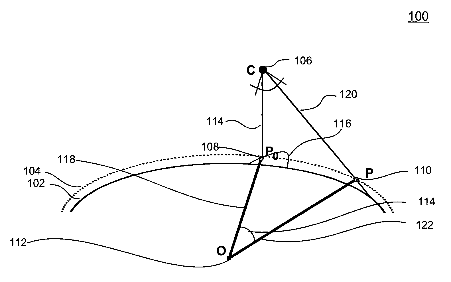
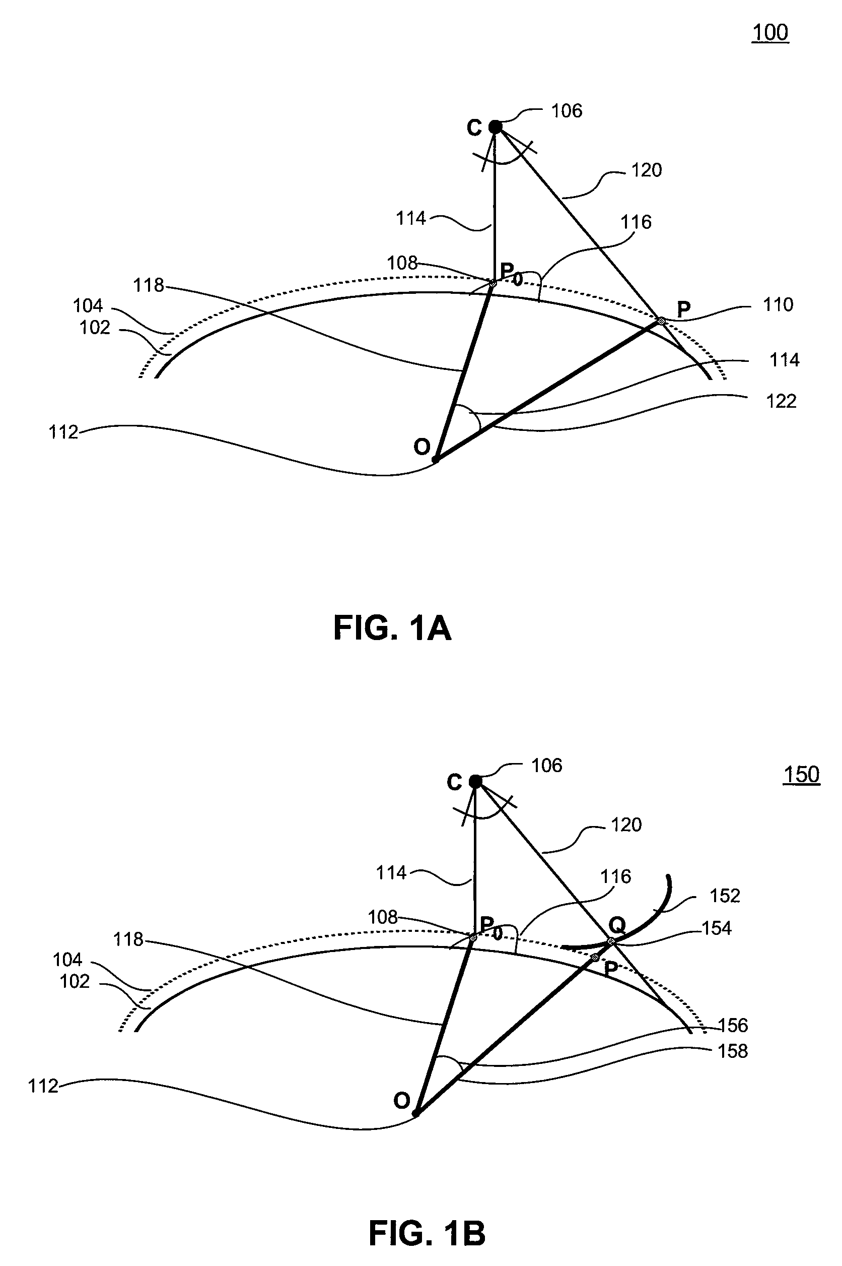
[0008]In a third embodiment, a computer-implemented method pans a virtual camera in a three dimensional environment that includes a three dimensional model of the Earth. The method includes: displaying in a display area the three dimensional model from a perspective of the virtual camera, enabling a user to select a first point on the display area with a cursor, and determining a first screen ray according to the first point. The method further includes: enabling the user to move the cursor to a second point in the display area, determining a second screen ray according to the second point, and rotating the three dimensional model around an axis through a rotation point (e.g., a center) of the three dimensional model to follow the cursor at a rate defined by a panning velocity. The panning velocity is a ratio of an angle of rotation of the three dimensional model to an angle between the first screen ray and the second screen ray. The panning velocity does not exceed a threshold value.

Problems solved by technology

As the virtual camera's perspective becomes tangential to the Earth, panning becomes increasingly unstable.
This can be disorienting for the user.

Method used


Image

  • Panning Using Virtual Surfaces
  • Panning Using Virtual Surfaces
  • Panning Using Virtual Surfaces

Examples


Embodiment Construction

[0023]Embodiments of the present invention relate to stable panning using virtual surfaces. In the detailed description of the invention that follows, references to “one embodiment”, “an embodiment”, “an example embodiment”, etc., indicate that the embodiment described may include a particular feature, structure, or characteristic, but every embodiment may not necessarily include the particular feature, structure, or characteristic. Moreover, such phrases are not necessarily referring to the same embodiment. Further, when a particular feature, structure, or characteristic is described in connection with an embodiment, it is submitted that it is within the knowledge of one skilled in the art to effect such feature, structure, or characteristic in connection with other embodiments whether or not explicitly described.

[0024]As used herein, the term “panning” a virtual camera refers to rotating a three dimensional model about an axis through a rotation point, such as its center. It is im...


PUM


Abstract

The present invention relates to panning a virtual camera in a three dimensional environment. In an embodiment of the present invention, a computer-implemented method pans a virtual camera in a three dimensional environment. In the method embodiment, a first point is determined on a three dimensional model in the three dimensional environment. According to the first point, the three dimensional model, and a position of a virtual camera in the three dimensional environment, a virtual surface is determined. A second point is determined on the virtual surface. Finally, a location of the three dimensional model is changed according to the first point and the second point.

Description

FIELD OF THE INVENTION[0001]The present invention relates to moving a virtual camera in a three dimensional environment.BACKGROUND[0002]Systems exist for navigating through a three dimensional environment to display three dimensional data. The three dimensional environment includes a virtual camera. The virtual camera has a perspective that defines what three dimensional data to display to a user. The user may input data that pans the virtual camera. By panning the virtual camera, the user navigates in the three dimensional environment.[0003]One type of system that pans a virtual camera to navigate in a three dimensional environment is a geographic information system. A geographic information system is a system for storing, retrieving, manipulating, and displaying a three dimensional model of the Earth. The three dimensional model may include satellite images texture mapped to terrain, such as mountains, valleys, and canyons. Further, the three dimensional model may include building...

Claims


Application Information

Patent Timeline
IPC IPC(8): G06T15/00G06T15/20
CPCG06T15/20
Inventor VARADHAN, GOKULBARCAY, DANIEL
Owner GOOGLE LLC
Learn More