As all of these appliances are portable and for table top use they are normally stored away in a
closet or the like, therefore they are
time consuming to retrieve, setup and breakdown for storage, thus they are seldom used when only a few items such as
meal leftovers could be vacuum packaged.
Another problem with these appliances is that the
vacuum chamber or vacuum
nozzle therein is in or near a horizontal position and not in the same plane with the table top the appliances are setting on.
Therefore, the vacuum bag filled with items rests down on the table top below the horizontal plane of the vacuum chamber or
nozzle, making it difficult to hold and maintain the open end of the bag in the vacuum chamber or
nozzle.
Even then, the vacuum bag's open end has the tendency to shift while the lid or hood is being closed over the open end of the bag, thus requiring additional positioning for proper vacuuming and sealing.
Another problem with horizontal positioned bags is a tendency to get debris from the content items around the inside edges of the bag where the bag is in contact with vacuum chamber seals and the heat strip wire, whereas the vacuum and seal can be negated due to
contamination.
Therefore, it is necessary to clean the inside surface of the bag with a towel when packaging contents that tend to be messy, therein requiring an additional step in the process of vacuuming and sealing a bag.
However, this appliance is designed to have the bag and contents horizontal on the inside of the appliance and the rod may not be a positive restraint for holding a bag in a vertical position.
One problem with this appliance is that one end of the bag must be held by one hand of the operator thereby leaving only one hand free to fill the bag, which in the case of some food items this could be very messy and present the potential of spilling said contents into the appliance.
Also, debris from the contents being filled can accumulate in the area of the bag where it is to be sealed and thereby cause the seal to fail.
Further, it is not recommended as there is no means to hold the open end of a vacuum bag in position of the vacuum chamber for vacuuming and sealing.
The problem with a nozzle orifice is that the rubber seals that creates the vacuum closure compresses around the nozzle orifice and eventually becomes distorted to where a vacuum is difficult to maintain before sealing the bag.
Further, Skerjanec's appliance could not be mounted under a shelf, cabinet or the like.
Further, these devices are all table top appliances with the vacuum chamber oriented in a horizontal plane and not intended for suspension under a shelf, cabinet or the like.
Further, there is no provision for holding the open end of the bag prior to closing the lid.
A problem encountered with vacuum chambers as well as vacuum nozzles has been that the open end of the vacuum bag is difficult to keep oriented correctly in the chamber.
This means requires special bags and is not adjustable for different width bags.
Further, this device has no vacuum chamber and can only be wall mounted.
This design requires complicated mechanical gears and levers.
Further, it could only hold one size bag and could not be mounted under a shelf, cabinet or the like, as the filler means rotates over the top of the device.
Also, this device is only for sealing a bag and provides no means for vacuum extracting
ambient air from the bag.
The problem with this devise is it is complicated with
moving parts and any contaminates from items being packaged in the horizontal position will have a tendency to contaminate the
moving parts of the clamps and make them inoperative.
Further, this appliance is for table use and cannot be mounted under a shelf, cabinet or the like.
The problem with this arrangement is evident in that the pull in pins 170a and 170b (Para ) engage the
front cover 154 and do not hold the vacuum bag until the
front cover is closed, requiring extensive mechanical and electrical components for its operation.
As the sensors are in the vacuum chamber (FIG. 15) they will get contaminated with any liquids from the contents in the vacuum bag during the evacuation of ambient.
In summary of Harrison's disclosures it is noted, that excessive mechanical, electrical and pneumatic components are required to accomplish the intended application by use of many
moving parts, springs, solenoids, latches, locking pins, bars,
control valves, check valves, sensors, bladders and magnets.
It would be evident that this device would be comparatively expensive to produce and requiring extensive maintenance and operator instructions.
As Harrison's illustrations are only outline drawings it may be difficult for any ordinarily skilled in the art to understand, make, and use the device.
The problem with Higer's device is that the hinged griping mechanism is in front of the vacuum chamber that holds the removable drip tray, exposing the hinged mechanism to
contamination from liquids being sucked into the vacuum chamber.
Higer's device requires excessive components such as, springs, latching mechanisms, bladders, hinges, magnets, shutters and balloons.
It would be evident that this device would be comparatively expensive to produce and require extensive maintenance and operator instructions.
As Higer's illustrations are only outline drawings it may be difficult for any ordinarily skilled in the art to understand, make, and use the device.
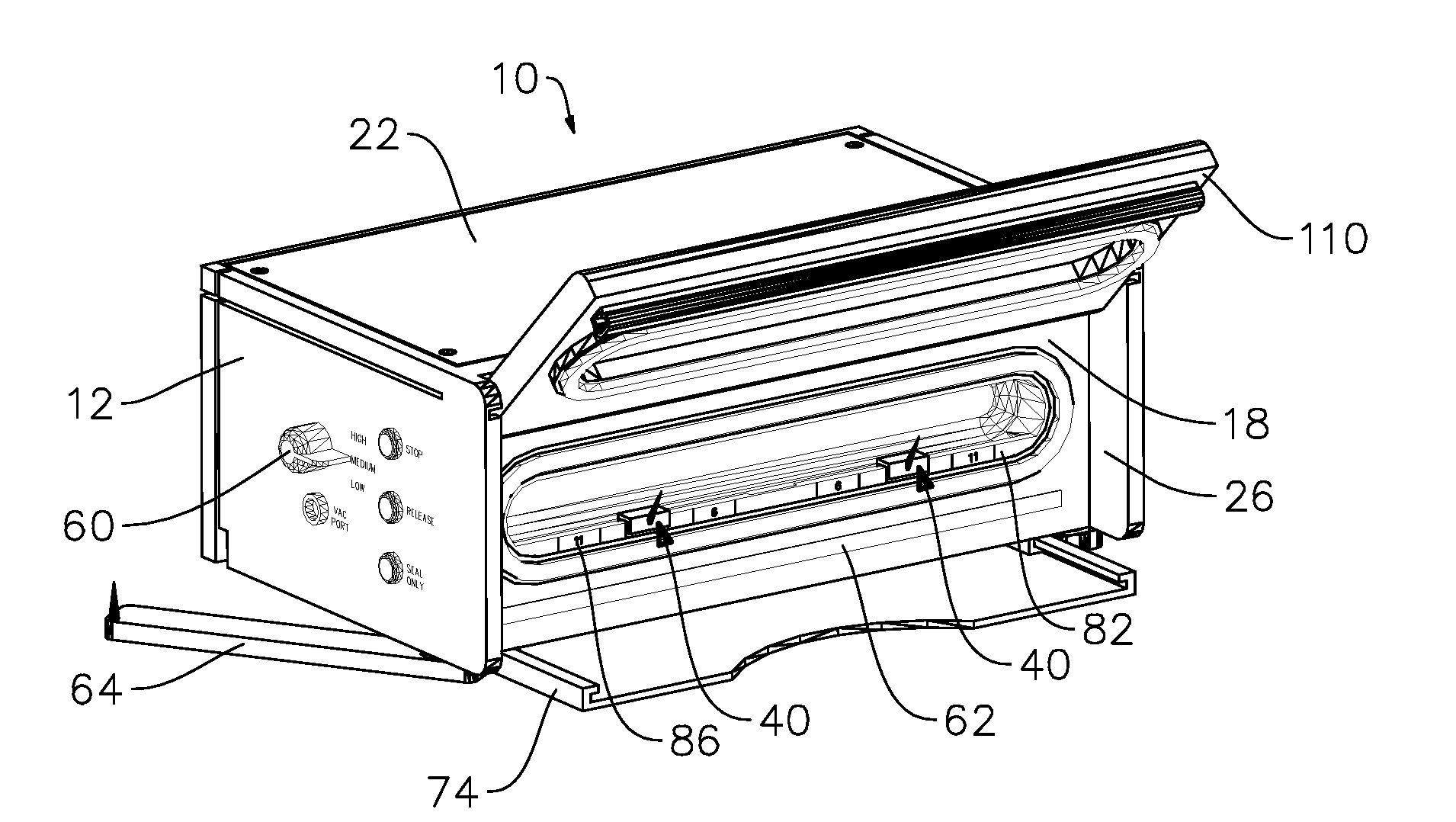
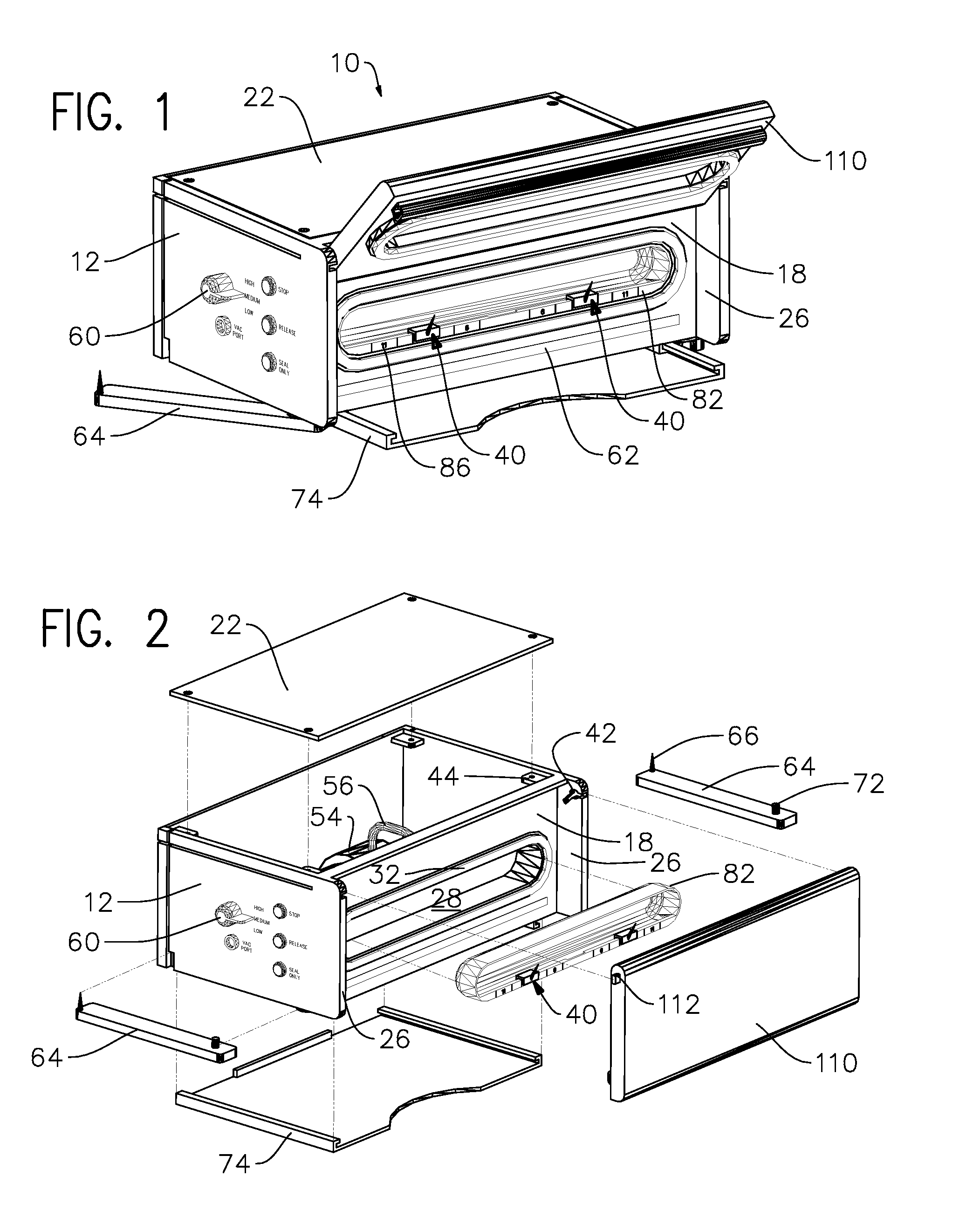
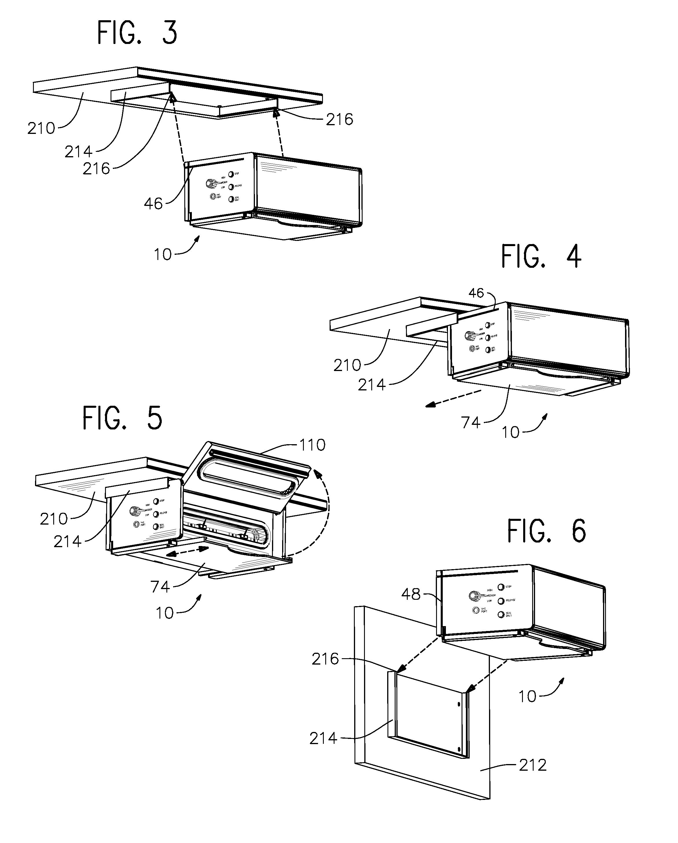
Heretofore, no known prior art addresses or discloses an engineered simplistic vacuum sealing appliance that provides for suspended mounting or attaching to the underside of a shelf, cabinet or the like and is easily removable.
Heretofore, no known prior art addresses or discloses a vacuum packaging sealing appliance that provides within the appliance a simple positive means for holding a bag suspended vertically for filling from outside of the appliance, wherein both hands of the operator are free to perform the filling operation.
Heretofore, no known prior art addresses or discloses a vacuum sealing appliance that provides a simple positive means for holding the open end of variable width filled vacuum bags in a vertical or near vertically oriented vacuum chamber opening.
Further, no known prior art addresses or discloses a vacuum sealing appliance that provides a means for storing a flat vacuum bag therein.


