Compression/distraction osteotomy system, plate, method, drill guide and saw guide

Inactive Publication Date: 2009-10-08
SKELETAL DYNAMICS LLC (US)
View PDF17 Cites 131 Cited by
  • Summary
  • Abstract
  • Description
  • Claims
  • Application Information

AI Technical Summary

Benefits of technology

[0011]It is accordingly an object of the invention to provide an osteotomy system, plate, method, drill guide and saw guide, which overcome the hereinafore-mentioned disadvantages of the heretofore-known devices and methods of this general type and which eliminate the need for additional devices, simplifying and speeding the surgical procedure and therefore reducing patient risk, as well as decreasing medical costs. More specifically, it is preferred that the device should not be cumbersome, should be almost entirely disposed within the body, should permit one plate to perform compression or distraction, should allow screws to be easily placed in a desired location and should allow for a variety of differently shaped planes resulting in different degrees of movement when contacted by screws.
[0022]In accordance with an additional embodiment of the invention, an anchoring screw may be tightened through a multi-angle screw hole in the plate body and through the second bone segment into the first bone segment after a desired amount of compression has been achieved. This is particularly useful in an oblique osteotomy where the screw placed through the multi-angle screw hole traverses both bone segments and aids in stabilization of the bone segments.
[0029]In accordance with another embodiment of an osteotomy system of the present invention, there is provided a saw guide for a step compression / distraction osteotomy plate, wherein the saw guide comprises an elongated body with a distal end portion, a proximal end portion, a center portion defining a first cutting plane, an adjustable plate defining a second cutting plane substantially parallel to the first cutting plane and an adjustment screw that threadably engages a threaded hole in the adjustable plate, while freely rotating within non-threaded holes provided at each end of a center portion of the saw guide. In the instant embodiment, turning a knob in the adjustment screw displaces the adjustable plate within the center portion of the saw guide along the longitudinal axis of the elongated body of the saw guide in such a way that the separation between the first cutting plane and the second cutting plane can be adjusted by the surgeon to the desired length of bone to be cut. If desired, a marking scale may be provided in the central body portion to indicate the separation between the first cutting plane and the second cutting plane.
[0031]In accordance with yet another embodiment of the invention, a saw guide is provided which includes a slotted keyhole at each of the distal end portion and the proximal end portion of the saw guide body. As used herein, the term “slotted keyhole” denotes an elongated hole or slot, wherein the opening at a first end is dimensioned to be larger than the opening at the second, opposite end, such that the head of a screw may freely pass through the first end opening, but not through the second end opening. The hole or slot is dimensioned to permit the screw's shaft to move freely from one end of the slot to the opposite end.
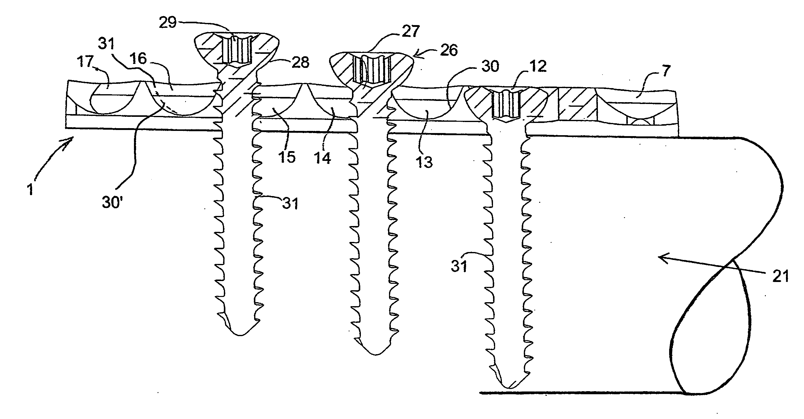
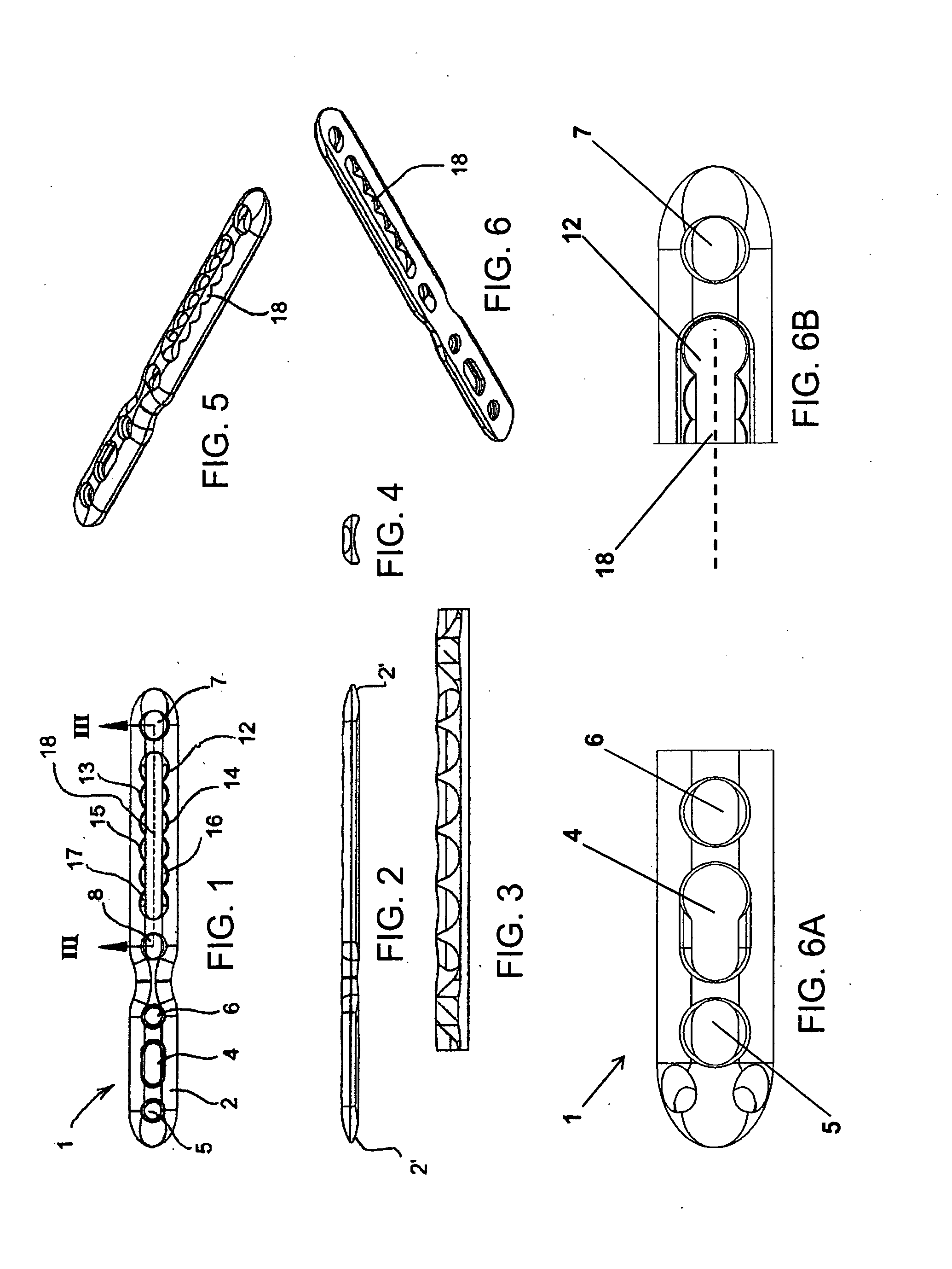
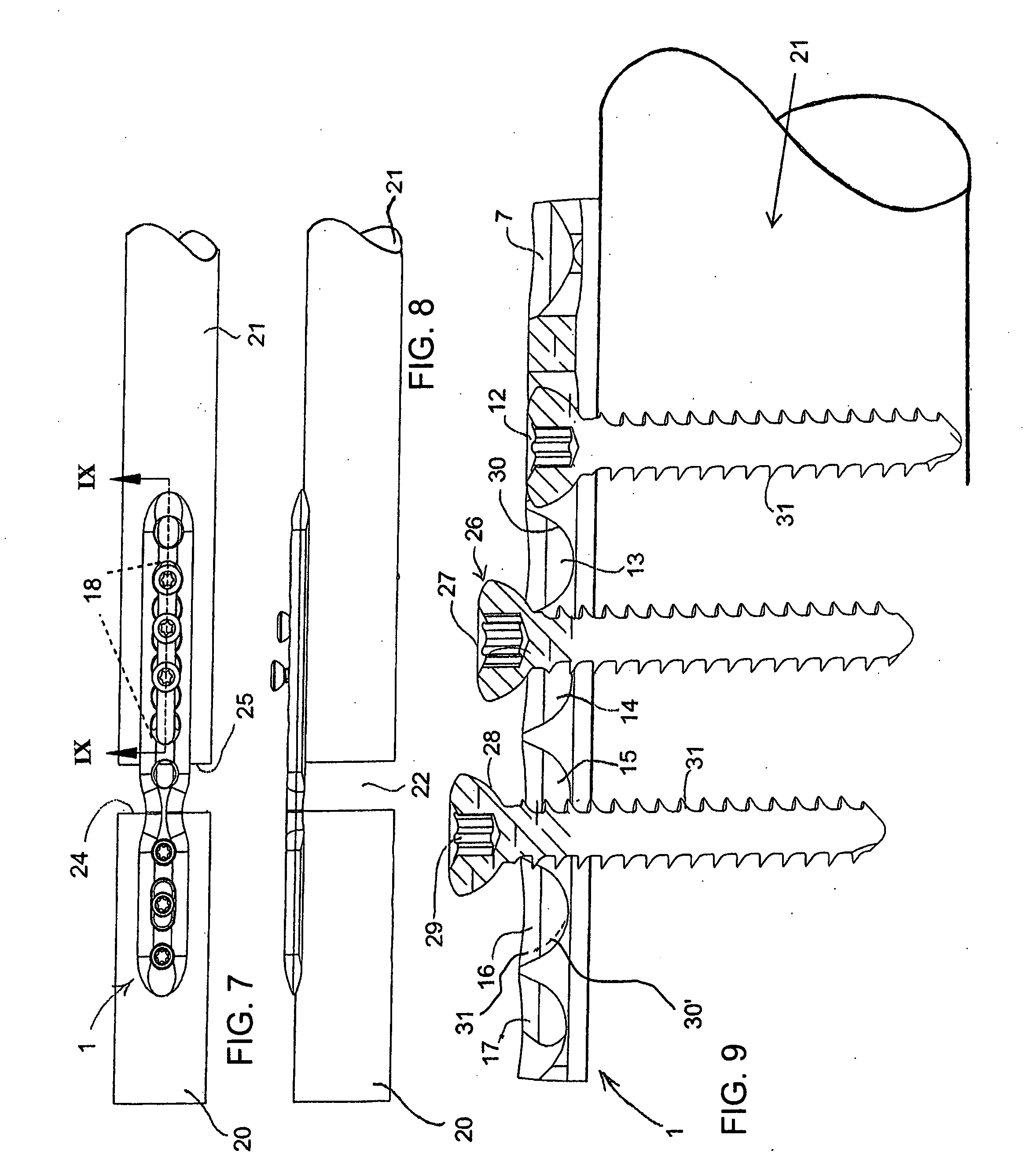
[0033]The osteotomy system of one particular embodiment of the present invention utilizes a combination step compression / distraction osteotomy plate including several advancement holes that may partially merge onto each other, in series, along a longitudinal slot on the plate. An osteotomy, creating two bone segments, may be performed by the surgeon free handed or, alternatively, with the aid of a saw guide. Tap holes for the advancement bone screws are drilled eccentrically using a drill guide or the saw guide. After fixing one end of the plate to a first bone segment an incremental advancement is obtained as the advancement screws are tightened and loosened sequentially into a second bone segment. In this manner, it is possible to advance the plate on the bone a large distance, compressing or distracting the bone segments. One of these advancement screws can remain as an anchoring screw after the bone translation is finished. The present system and method of allowing compression and / or distraction of an osteotomy facilitates the use of a smaller incision and reduces the number of procedural steps, time, and instruments that the procedure requires.

Problems solved by technology

Some current devices achieve compression or distraction by the use of cumbersome compression or distraction assemblies which are attached to the bone plate during the procedure, and are subsequently removed upon securing the plate to the bone.
Other existing devices are capable of achieving compression of two bone segments by use of eccentrically drilled screw holes providing what is called DCP (Dynamic Compression Plate) action, but available DCP technology cannot reposition the bone segments beyond 1-2 mm.
The device is cumbersome and requires a large incision since much of the device is located outside the body.
That device is also cumbersome and requires the blocks and screws to be placed outside of the body, once again requiring a large wound.
Therefore, even those prior art devices that are not as cumbersome do not permit both compression and distraction using the same plate, but rather, require a different plate for each function.

Method used


Image

  • Compression/distraction osteotomy system, plate, method, drill guide and saw guide
  • Compression/distraction osteotomy system, plate, method, drill guide and saw guide
  • Compression/distraction osteotomy system, plate, method, drill guide and saw guide

Examples


Embodiment Construction

[0071]Referring now to the figures of the drawings in detail and first, particularly, to FIGS. 1-6B thereof, there is seen a step compression / distraction osteotomy plate 1 having a plate body 2 with a distal end 2′, a proximal end 2″, a slotted keyhole 4, anchoring screw holes 5, 6, 7, a multi-angle screw hole 8 and first through sixth advancement / distraction screw holes 12-17, formed therein, according to a first embodiment of the invention. Note that, although six advancement / distraction screw holes are illustrated in connection with the present embodiment, this is not meant to be limiting, as fewer or more advancement / distraction screw holes may be used will still keeping with the principles of the present invention. As is best seen in FIG. 5 and FIGS. 6 and 6B although the screw holes 12-17 have discrete curved surfaces, they are also interconnected and merge into one another along a continuous slot 18, permitting screws to be partially screwed-in between the holes and also perm...


PUM


Abstract

An osteotomy system includes anchoring screws and advancement screws having a head with a surface defining a first angled plane. A plate has anchoring holes and advancement holes with countersunk surfaces defining respective second angled planes for compression or distraction. The first angled plane contacts one of the second angled planes upon tightening an advancement screw, causing advancement of the plate and step compression or distraction of one bone segment relative to another. In another embodiment, a wedge has a surface defining a first angled plane. A plate has one portion with inclined surfaces defining second angled planes. An advancement screw tightens the first angled plane against one of the second angled planes to advance one of the plate body portions for compression or distraction of one bone segment attached thereto relative to another segment. A plate, a method, a drill guide and a saw guide are also provided.

Description

REFERENCE TO RELATED APPLICATION[0001]The present application claims priority to the co-pending Provisional Patent Application No. 61 / 042,423, filed on Apr. 4, 2008 and entitled “Compression / Distraction Osteotomy System, Plate, Method and Drill Guide”, which application is being incorporated herein, by reference, in its entirety.BACKGROUND OF THE INVENTION[0002]1. Field of the Invention[0003]The invention relates to an osteotomy system and plate, as well as a method for operating the system, the plate, a drill guide and a saw guide. Osteotomy is used, in particular, to surgically divide or section bone, reposition the bone segments, and then stabilize the segments by attaching a bone plate. In certain cases, the osteotomy may be performed at an oblique angle (oblique osteotomy). Typical osteotomy procedures are used in the compression of the ulna bone and distraction of the radius bone to correct deformities of the upper extremity.[0004]2. Description of the Related Art[0005]Some cu...

Claims


Application Information

Patent Timeline
IPC IPC(8): A61B17/66A61B17/80A61B17/86A61B17/58A61F5/00
CPCA61B17/151A61B17/1728A61B17/8004A61B17/1739A61B17/8014A61B17/8023A61B17/8033A61B17/8009
Inventor ORBAY, JORGE L.NORMAN, THOMAS H.DE QUEVEDO, WILLIAM GARCIA
Owner SKELETAL DYNAMICS LLC (US)
Why Eureka
Try Eureka