
Recognition system, recognition method, and recognition program

a recognition system and recognition method technology, applied in the field of recognition systems, can solve problems such as false specific pattern suppression, and achieve the effect of reducing the appearance of false specific pattern

Active Publication Date: 2009-10-08
NEC CORP
View PDF1 Cites 12 Cited by
  • Summary
  • Abstract
  • Description
  • Claims
  • Application Information

AI Technical Summary

Benefits of technology

[0016]A first effect is that it is possible to suppress the phenomenon that a false specific pattern appears around a true specific pattern, which has generally been a problem when using the Hough transform.
[0017]The reason therefor is that a Hough space is designed so that a magnitude relation of a distance between points in the Hough space is equivalent to a predetermined magnitude relation of an inter-specific-pattern distance indicative of a difference between specific patterns, and thus, more si

Problems solved by technology

The conventional recognition system can suppress a phenomenon that a false straight-line component appears around a true straight-line component, which has generally been a problem when using the Hough transform.

Method used


Image

  • Recognition system, recognition method, and recognition program
  • Recognition system, recognition method, and recognition program
  • Recognition system, recognition method, and recognition program

Examples


first embodiment

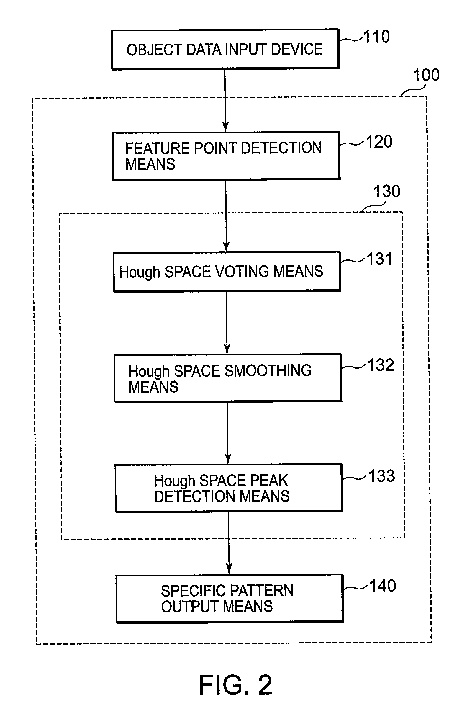
[0034]Referring to FIG. 2, this invention comprises a computer (central processing unit; processor; data processing unit) 100 operated under program control and an object data input device 110.

[0035]The computer (central processing unit; processor; data processing unit) 100 includes feature point detection means 120, Hough transform means 130, and specific pattern output means 140.

[0036]The Hough transform means 130 comprises Hough space voting means 131, Hough space smoothing means 132, and Hough space peak detection means 133.

[0037]These means respectively operate as follows.

[0038]The object data input device 110 inputs data being a detection object for desired specific patterns.

[0039]The feature point detection means 120 detects, as feature points, those points presumed to be points on the specific patterns from the object data.

[0040]In a space with the axes representing parameters that express the specific patterns (hereinafter referred to as a Hough space), the Hough space voti...

second embodiment

[0092]Referring to FIG. 10, a recognition system according to this invention comprises a computer (central processing unit; processor; data processing unit) 900 operated under program control and an object data input device 910.

[0093]The computer (central processing unit; processor; data processing unit) 900 includes feature point detection means 920, Hough transform means 930, and specific pattern output means 940.

[0094]The Hough transform means 930 comprises Hough space voting means 931, Hough space smoothing means 932, and Hough space peak detection means 933.

[0095]These means respectively operate as follows.

[0096]The object data input device 910 inputs data being a detection object for desired specific patterns.

[0097]The feature point detection means 920 detects, as feature points, those points presumed to be points on the specific patterns from the object data.

[0098]In a Hough space expressing the specific patterns, the Hough space voting means 931 votes weights corresponding t...


PUM


Abstract

A recognition system of this invention has feature point detection means (120), Hough transform means (130), and specific pattern output means (140). In the Hough transform means (130), a Hough space is designed so that a magnitude relation of a distance between points in the Hough space is equivalent to a predetermined magnitude relation of an inter-specific-pattern distance indicative of a difference between specific patterns. The recognition system detects the specific patterns using the Hough space. By adopting such a structure to express more similar specific patterns in an image as closer points also in the Hough space, it is possible to achieve an object of this invention.

Description

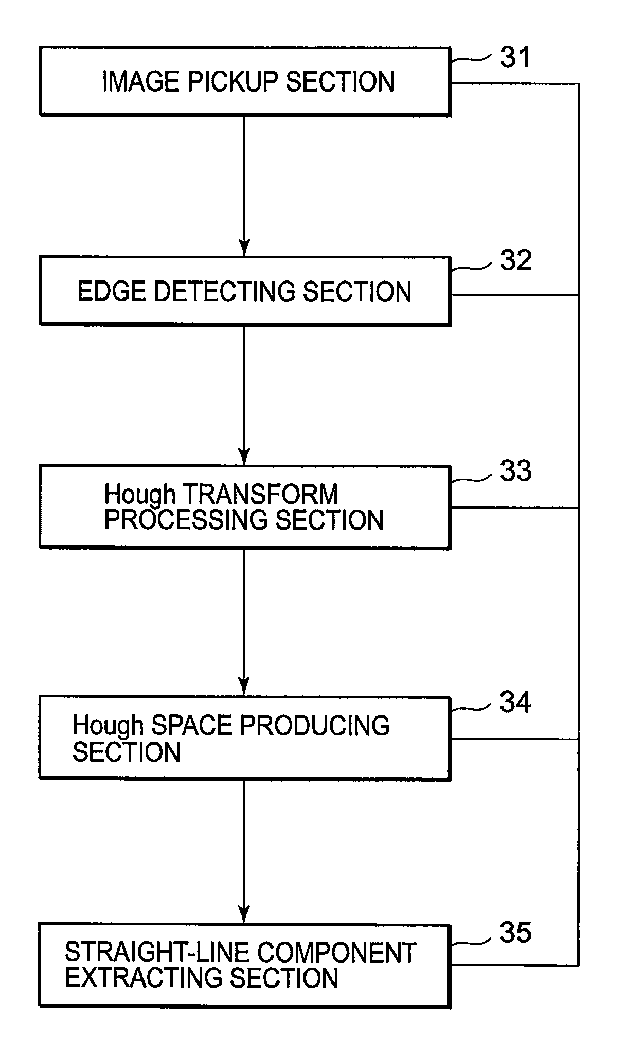
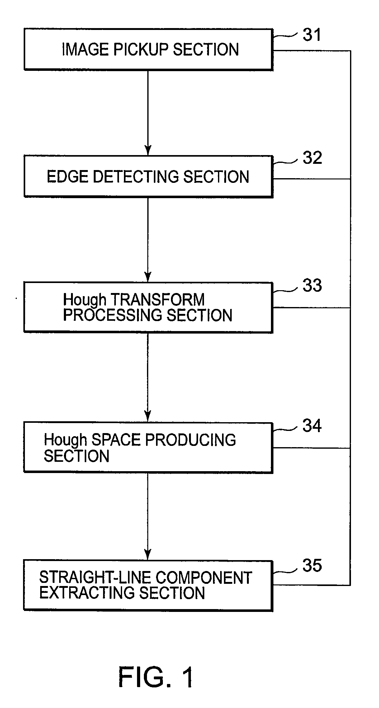
TECHNICAL FIELD[0001]This invention relates to a recognition system, a recognition method, and a recognition program and, in particular, relates to a recognition system, a recognition method, and a recognition program that are strong against noise and are capable of preventing overdetection detecting, as a recognition object specific pattern, a partial region other than the recognition object specific pattern.BACKGROUND ART[0002]One example of conventional recognition systems is described in Japanese Unexamined Patent Application Publication (JP-A) No. Hei 6-314339 (Prior Art Document 1). This conventional recognition system detects a straight line as a specific pattern from an image as object data. The conventional recognition system can suppress a phenomenon that a false straight-line component appears around a true straight-line component, which has generally been a problem when using the Hough transform.[0003]As shown in FIG. 1, this conventional recognition system comprises an ...

Claims


Application Information

Patent Timeline
IPC IPC(8): G06K9/46G06K9/36G06V10/48
CPCG06K9/4633G06K9/00798G06V20/588G06V10/48
Inventor SAKURAI, KAZUYUKI
Owner NEC CORP
Learn More