
Enhanced concentrator PV pannel

a concentrator and concentrator technology, applied in the field of photovoltaic technology, can solve the problems of not being able to provide a wide angle of view with a sufficiently high concentration ratio, still cost-effective to use more expensive and higher efficiency cells, and thus being much limited, so as to reduce optical length and increase concentratio

Inactive Publication Date: 2009-10-08
CHEN ZUPEI
View PDF4 Cites 33 Cited by
  • Summary
  • Abstract
  • Description
  • Claims
  • Application Information

AI Technical Summary

Benefits of technology

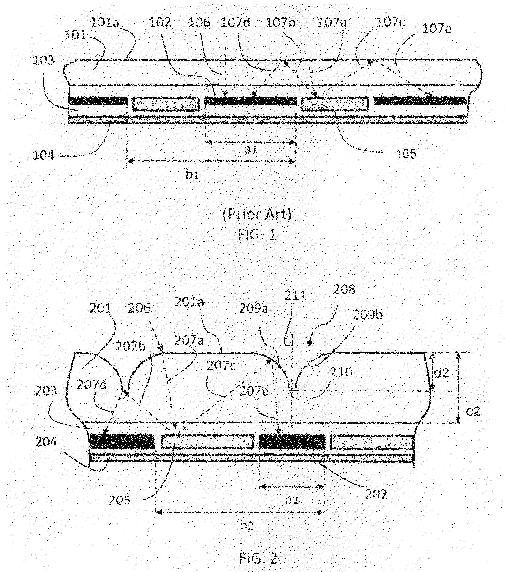
[0011]The present invention teaches a concentrator PV panel with a small view angle not less than 40 degree and a large view angle equal to 180 degree, perpendicular to each other that satisfies a fixed ground solar generation system application criteria. The PV panel includes rows of PV cell or a linear array of PV cells connecting in series and / or in parallel, alternating with rows of optical reflective beam splitters. The PV cell rows and beam splitter rows completely covers the light-incident surface of the PV panel. The PV cell array is sandwiched in between a transparent cover plate and a back plate using an adhesive. The back plate is insulating and humidity-proof. To reduce the optical length and increase concentration ratio, rows of grooves with flat or curved sidewalls are formed on the front surface of the transparent cover plate, each of which being parallel to and above of a PV cell row. A humidity protected mirror is attached on the back surface of the back plate.

Problems solved by technology

Since concentrator PV systems require less semiconductor material to capture a given amount of sunlight, it is still cost-effective to use more expensive and higher efficiency cells to increase the electricity generated from a given collection area.
Those approaches fail to provide wide angle of view with sufficiently high concentration ratio and thus are much limited.

Method used


Image

  • Enhanced concentrator PV pannel
  • Enhanced concentrator PV pannel
  • Enhanced concentrator PV pannel

Examples


Embodiment Construction

[0027]While the present invention may be embodied in many different forms, designs or configurations, for the purpose of promoting an understanding of the principles of the invention, reference will be made to the embodiments illustrated in the drawings and specific language will be used to describe the same. It will nevertheless be understood that no limitation of the scope of the invention is thereby intended. Any alterations and further implementations of the principles of the invention as described herein are contemplated as would normally occur to one skilled in the art to which the invention relates.

[0028]Referring to FIG. 1, which is a schematic fragmentary diagram illustrating a sectional view of a flat plate PV panel according to the prior art, the PV panel includes a cover glass 101, a water proof back plate 104, and an array of PV cells, such as 102, which is sandwiched between the cover glass 101 and the water proof back plate 104 by a transparent and insulative adhesive...


PUM


Abstract

The invention teaches a family of flat concentrator PV panels wherein an array of enhanced light beam splitters coupling with a plurality of optical grooves efficiently collects light and transmits collected light substantially to the active surface(s) of an array of size-reduced PV cells with low aspect ratio.

Description

REFERENCE TO RELATED APPLICATION[0001]The present application claims priority to the provisional Appl. Ser. No. 61 / 123,437 filed on Apr. 8, 2008, the entire content of which is hereby incorporated by reference.FIELD OF THE INVENTION[0002]The present invention relates in general to photovoltaic technology. More particularly, the invention relates to a flat concentrator PV panel in which an array of enhanced light beam splitters coupling with a plurality of optical grooves efficiently collects light and transmits collected light substantially to the active areas of an array of size-reduced photovoltaic cells with a low aspect ratio.BACKGROUND OF THE INVENTION[0003]Flat plate Photovoltaic (PV) panel is a system that produces electricity by having sunlight directly strike PV cells made of expensive semiconductor material.[0004]To reduce the cost, concentrator PV panel which requires less PV cell consumption is being highlighted in today's market. Concentrator PV technologies use relativ...

Claims


Application Information

Patent Timeline
Patent Type & Authority Applications(United States)
IPC IPC(8): H01L31/042
CPCH01L31/068H01L31/0547Y02E10/547Y02E10/52
Inventor CHEN, ZUPEI
Owner CHEN ZUPEI
Learn More