
Ankle stabilizer

a stabilizer and ankle technology, applied in the field of orthopedic medical devices, can solve the problems of slow rehabilitation and promote muscle atrophy, lack of performance, and bulky braces,

Inactive Publication Date: 2009-10-01
LUNDBERG LESLIE C
View PDF29 Cites 26 Cited by
  • Summary
  • Abstract
  • Description
  • Claims
  • Application Information

AI Technical Summary

Benefits of technology

[0011]Embodiments of the present invention provide an ankle stabilizer that does not suffer from the problems and limitations of the prior art ankle wraps, sleeves, and braces set forth above.

Problems solved by technology

These ligaments are prone to various types of high and low ankle sprains caused by excessive foot movement, such as eversion (when the foot is turned outwardly relative to the leg and causes undue stretching of medial ligaments) or inversion (when the foot is turned inwardly relative to the leg and causes undue stretching of lateral ligaments) of the ankle.
However, this type of brace is typically bulky and therefore cannot be worn inside a shoe or clothing.
Another serious problem with a “splint-type” brace is that essentially all joint function is prevented, which restricts activity involving use of the joint and can thereby slow rehabilitation and promote muscle atrophy.
Wrapping of the joint with a cloth bandage or tape is another conventional technique for immobilizing a joint Although cloth or tape wraps are more comfortable and less bulky than “splint-type” braces, the wraps likewise immobilize the joint and therefore present the same problems of atrophy, lack of performance during the rehabilitation stage of the injury, and excessive restriction of joint function.
Cloth and tape wraps are particularly problematic because they encircle the joint and adjacent body parts, such as the top of the foot, and also preclude necessary dorsi and plantar flexion of the ankle joint.
Although this type of brace is comfortable and capable of being worn within a shoe, the sleeve itself provides little support to the joint.
Accordingly, the sleeve would not be effective during the acute stage of an injury because of its failure to sufficiently restrict movement of the joint.
Even when the sleeve is used for rehabilitative purposes, it restricts movement of the joint in virtually any direction and, consequently, fails to permit dorsiflexion and plantar flexion of the foot.
However, this type of brace still presents the same problems noted above.

Method used


Image

  • Ankle stabilizer
  • Ankle stabilizer
  • Ankle stabilizer

Examples


Embodiment Construction

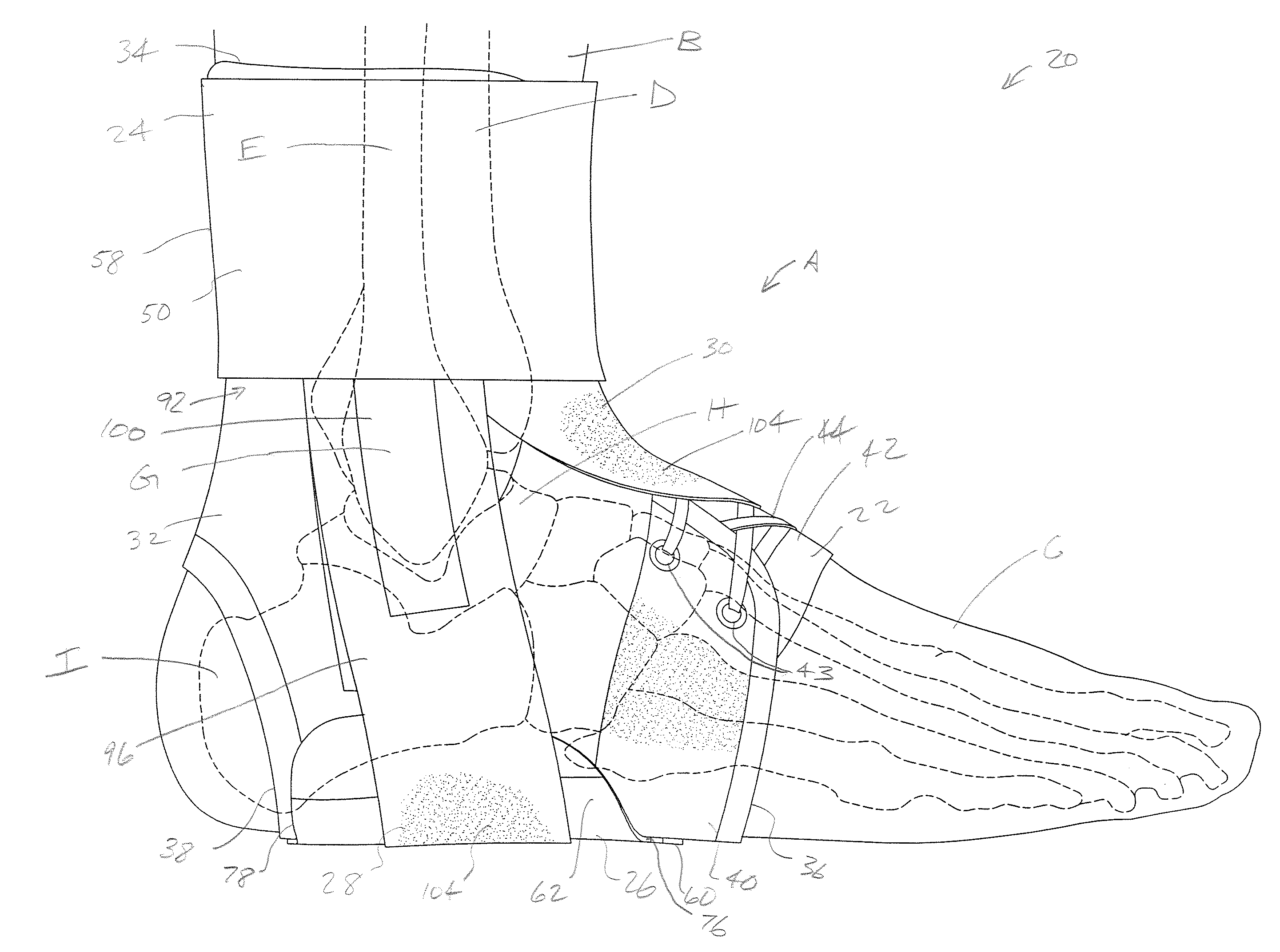
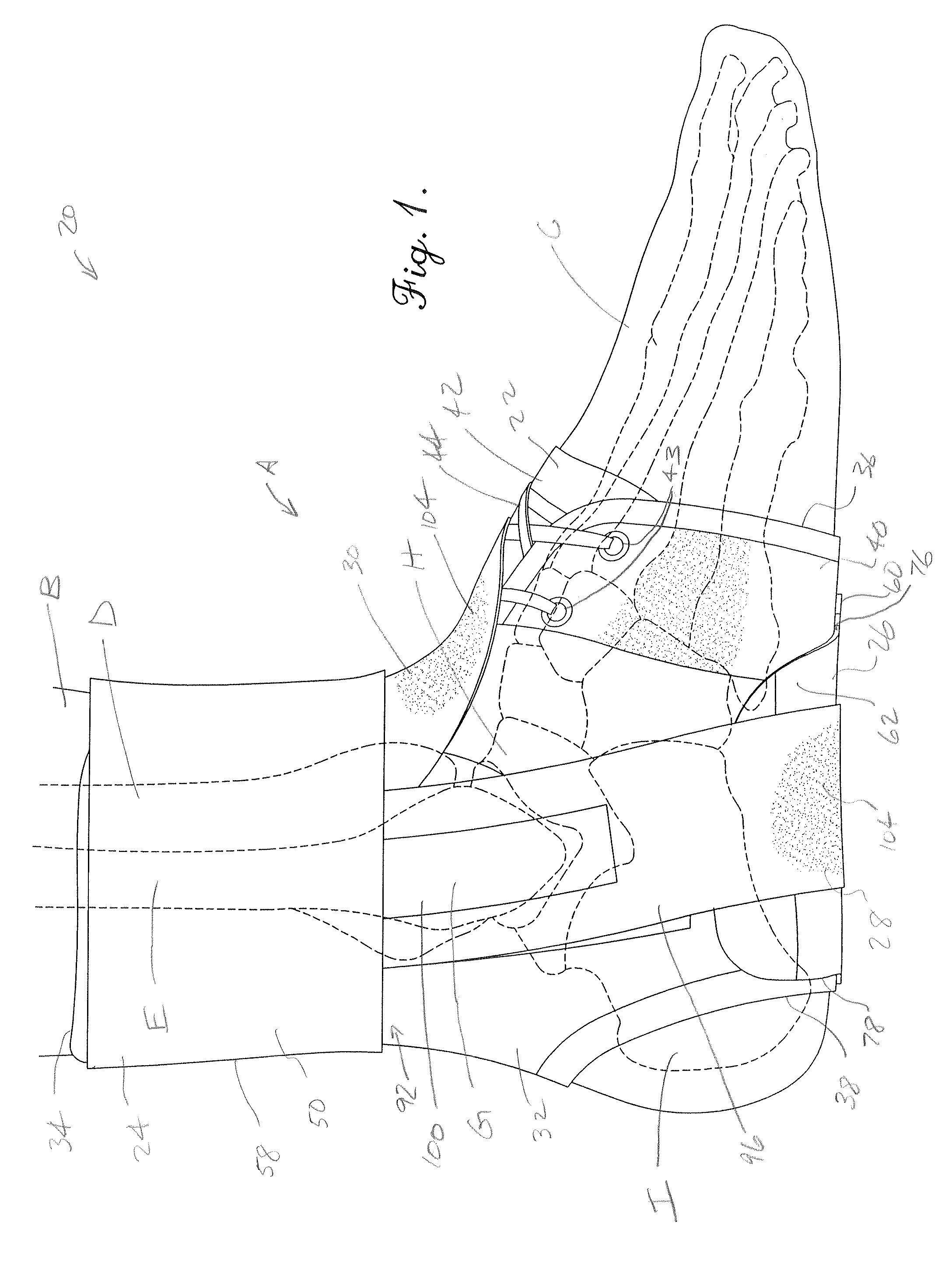
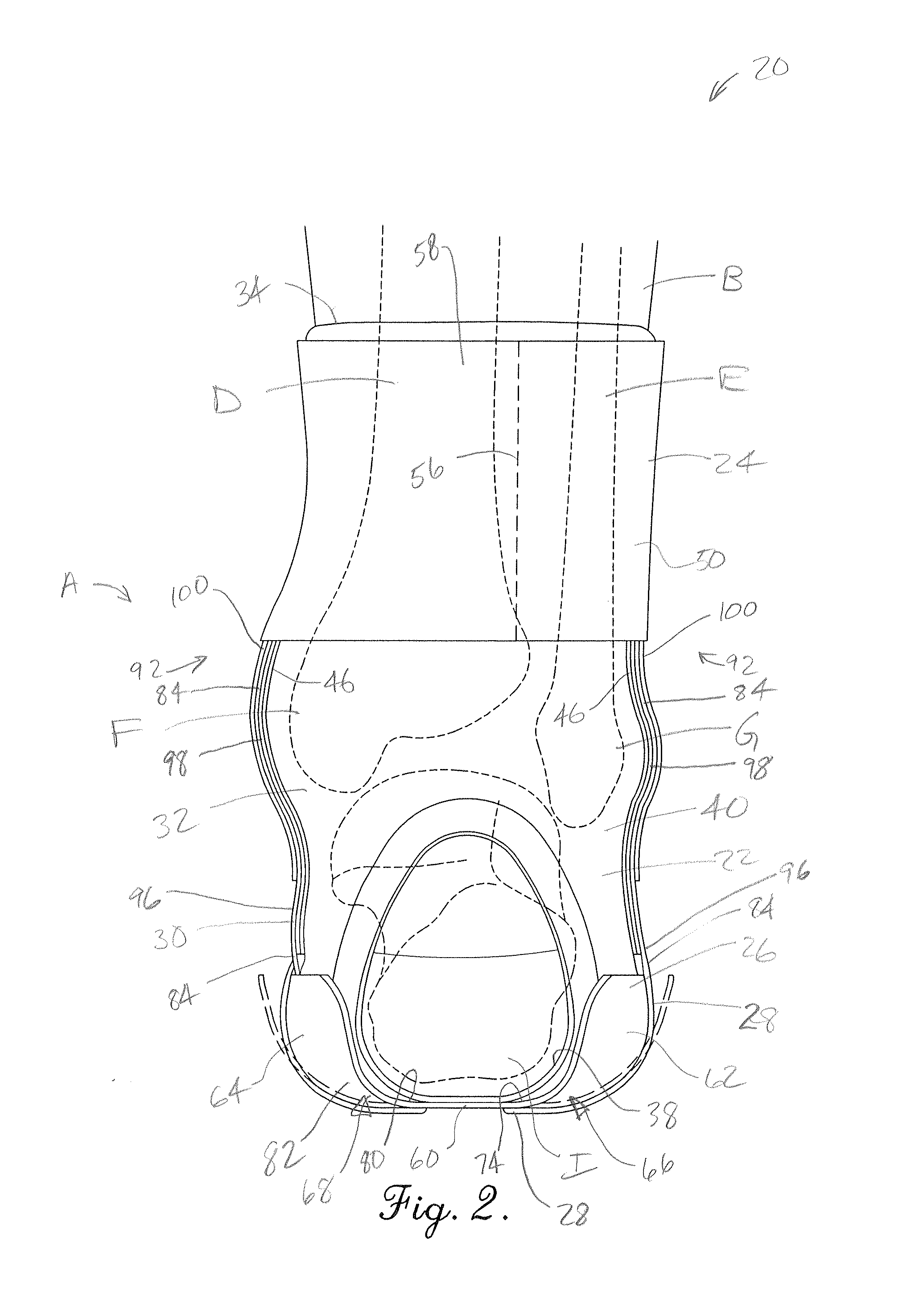
[0035]Turning initially to FIGS. 1 and 2, a synovial ankle joint A of the human body is generally formed between the leg B and the foot C. The ankle joint A includes a number of bones that generally connect the foot C to the tibia D and fibula E of the leg B. For instance, the tibia D and fibula E present corresponding medial and lateral malleoli F,G that are attached to the talus H and calcaneous I. The ankle joint A is flexible in a number of directions including inversion (where the foot is turned inwardly relative to the leg and which can result in undue stretching of lateral ligaments), eversion (where the foot is turned outwardly relative to the leg and which can result in undue stretching of medial ligaments), dorsiflexion (where the anterior end of the foot is turned upwardly relative to the heel) and plantar flexion (where the anterior end of the foot is turned downwardly relative to the heel). Although several foot joints adjacent the heel permit these movements, the words...


PUM


Abstract

An ankle brace is configured to provide lateral and / or medial support of an ankle joint between the leg and foot and broadly includes an upper brace anchor secured to the leg above malleoli of the ankle joint and a lower brace anchor secured below the foot. The anchors are interconnected by a stabilizing strap that is tensioned between the anchors and serves to restrict inversion and / or eversion of the foot. The anchors and strap are also dimensioned and configured to permit dorsiflexion and plantar flexion of the foot.

Description

RELATED APPLICATION[0001]This application claims the benefit of U.S. Provisional Application Ser. No. 61 / 072,251, filed Mar. 28, 2008, entitled ANKLE STABILIZER, which is hereby incorporated in its entirety by reference herein.BACKGROUND[0002]1. Field[0003]The present invention relates generally to orthotic medical devices. More specifically, embodiments of the present invention concern an ankle stabilizer that supports an ankle joint by restricting inversion and / or eversion of the foot while permitting plantar flexion and / or dorsiflexion of the foot.[0004]2. Discussion of Prior Art[0005]The ankle comprises a synovial joint and connects the foot to the tibia and fibula of the leg. The ankle and foot include numerous bones that are interconnected by ligaments, muscles, and other tissues. These ligaments are prone to various types of high and low ankle sprains caused by excessive foot movement, such as eversion (when the foot is turned outwardly relative to the leg and causes undue st...

Claims


Application Information

Patent Timeline
IPC IPC(8): A61F5/00
CPCA61F5/0111
Inventor LUNDBERG, LESLIE C.
Owner LUNDBERG LESLIE C
Learn More