
Electronic display device with integrated lighting system

Active Publication Date: 2009-10-01
LYNK LABS INC
View PDF37 Cites 7 Cited by
  • Summary
  • Abstract
  • Description
  • Claims
  • Application Information

AI Technical Summary

Benefits of technology

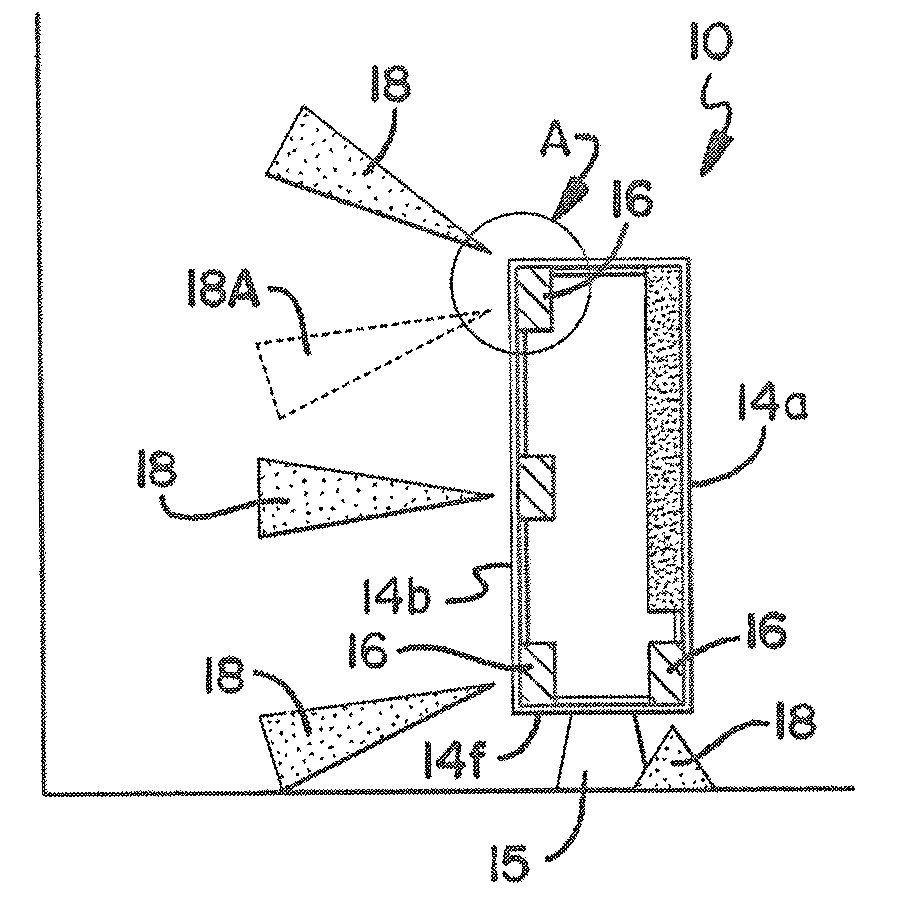
[0009]Broadly, an embodiment of the present invention includes an electronic visual display with a housing and one or more lighting devices integrated therewith. The housing and the one or more lighting devices are cooperatively configured and shaped with respect to each other to enable the secure mounting and attachment of the one to the other as an integrated unit for consumer use while permitting an orientation of the one or more lighting devices so as to provide direct light to one or more spaces external to the electronic visual display. Both the electronic visual display and the one or more lighting devices have an on state and an off state that are independently selectable by an end user. Such a configuration allows an end user to selectably place the one or more lighting devices in an on state to provide light while the electronic visual display is in an off sate or vice versa. Regardless of whether the electronic visual display is in the on or the off state, the one or more lighting devices provide a relatively constant color and relatively constant level of light output when in their “on state.”
[0011]In an embodiment of the present invention a user interface is provided which allows an end user to select certain lighting devices among all of the integrated lighting devices to be in an on state while others are in an off state.

Problems solved by technology

One problem associated with these displays is eye strain based upon the light output of the display and / or inadequate lighting in the viewing area.
The available space required for both products then becomes an issue for coordinated use of the products and any other use to be made of the space.
In addition the optimum lighting for an area functionally (e.g. enhancing the view or viewability of the electronic display) or aesthetically, is compromised by the fact that the two devices conflict spatially or locationally, and by virtue of their independent design.
For example: a shadow (caused by the display) will exist on the right side of a display when a table top lamp is placed on the left side of the display; a shade for a lamp may not allow it to direct light to the area behind the display device if desired; and a lamp with a clamp-on or other generic connector, is just aesthetically displeasing wherever it may be temporarily clamped, and may not match with a suitable cooperative surface for clamping securely.
In addition, power requirements becomes an issue since mains outlets are spaced by most municipal codes and both products (lighting and display) require a connection to the mains.
If both products are “plugged in” then a typical outlet is insufficient for connecting other products to power.
However, when the display is turned of—a consumer may have insufficient light to navigate to a lighted area, or to a switch to turn on a general lighting device for the room or area.

Method used


Image

  • Electronic display device with integrated lighting system
  • Electronic display device with integrated lighting system
  • Electronic display device with integrated lighting system

Examples


Embodiment Construction

[0032]While the present invention is capable of embodiment in many different forms, there is shown in the drawings and will herein be described in detail, preferred embodiments of the invention with the understanding that the present disclosure is to be considered as an exemplification of the principles of the invention and is not intended to limit the broad aspect of the invention to the embodiments illustrated.

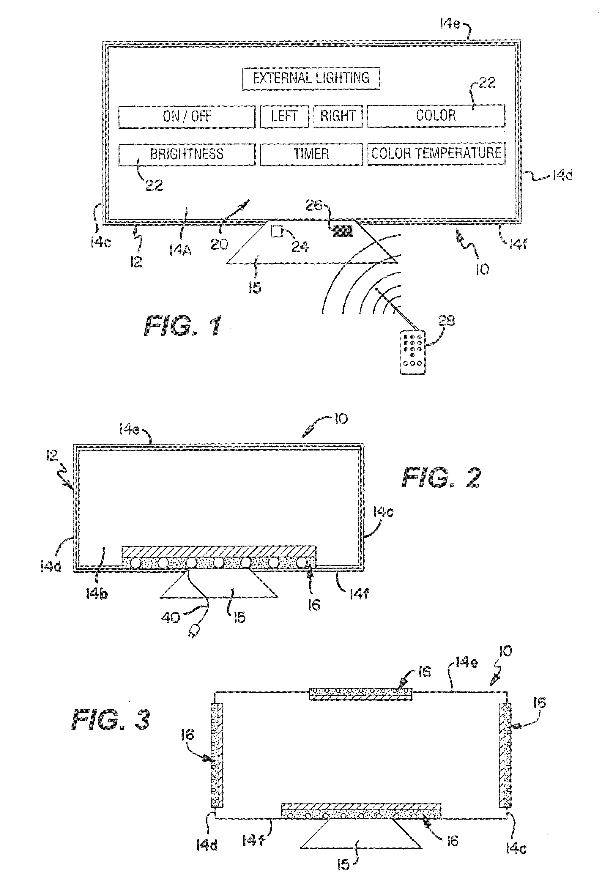
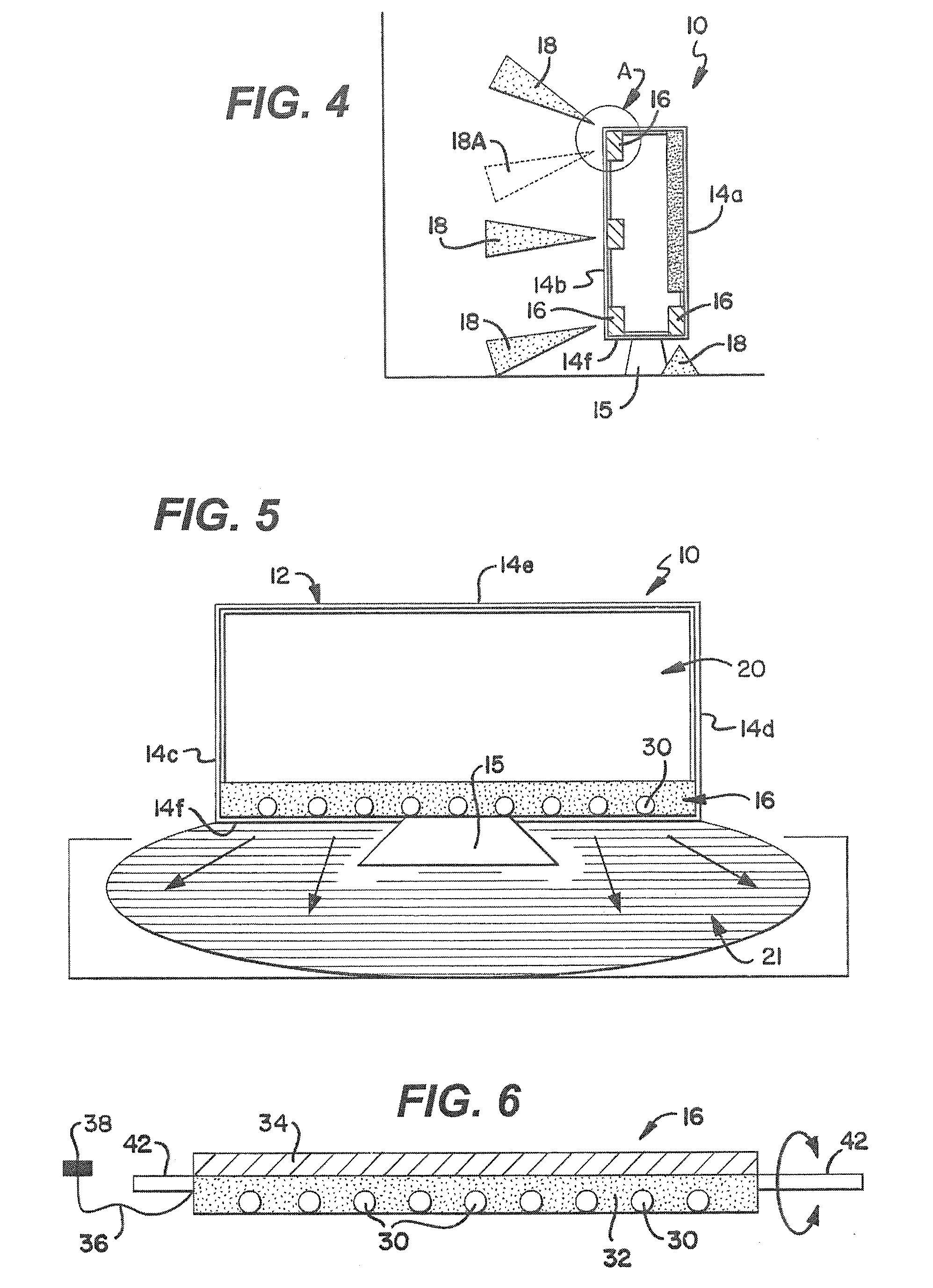
[0033]FIGS. 1-5 disclose an electronic visual display system with an integrated lighting system 10, having various embodiments of lighting devices 16. System 10 includes an electronic visual display 12 having a housing 14.

[0034]FIG. 2 discloses a first embodiment of system 10 having one lighting device 16, while FIG. 3 discloses a second embodiment of system 10 with four lighting devices 16. FIG. 4 in turn discloses a third embodiment of system 10 having four lighting devices 16 in a different arrangement than the four lighting devices 16 in the second embodiment of FIG. 3. ...


PUM


Abstract

An electronic visual display system with an integrated general lighting system including an electronic visual display having a housing and one or more lighting devices integrated therewith to provide light to one or more spaces external to the electronic visual display housing. The lighting devices have an independent on and off state which allows for the lighting devices to be in the on state independent of the on and off state of the electronic visual display. The lighting devices provide a relatively constant and user selectable color and level of light output.

Description

PRIORITY AND RELATED APPLICATIONS[0001]This Application Claims priority to U.S. Provisional Application No. 61 / 072,475 entitled Computer Display Work Lighting System Method And Apparatus filed Mar. 31, 2008 and U.S. Provisional Application No. 61 / 208,291 entitled Display With Integrated General Lighting System Method And Apparatus filed Feb. 23, 2009. The contents of these Applications are incorporated herein by reference.FIELD OF THE INVENTION[0002]The present invention relates to portable or semi portable lighting devices and fixtures for general lighting such as: table and floor lamps; task lighting; under-cabinet lighting; and track lighting, and to electronic visual display devices which are portable or semi-portable such as: digital photo albums; desktop and portable computers; and, plasma and liquid crystal (LCD) television displays.BACKGROUND OF THE INVENTION[0003]Electronic visual displays are pervasive in modem society in use for displaying information and entertainment co...

Claims


Application Information

Patent Timeline
IPC IPC(8): F21V21/00G08C19/00G06F3/048F21V7/00
CPCH04N9/73G06F1/1601
Inventor MISKIN, MICHAEL
Owner LYNK LABS INC
Learn More