
Robot drive with magnetic spindle bearings

a technology of magnetic bearings and robot drives, which is applied in the direction of mechanical control devices, instruments, process and machine control, etc., can solve the problems of motor feedback malfunction, limited grease use for lubricating the robot drive bearings, and grease contamination

Active Publication Date: 2009-10-01
BOOKS AUTOMATION US LLC
View PDF99 Cites 124 Cited by
  • Summary
  • Abstract
  • Description
  • Claims
  • Application Information

AI Technical Summary

Problems solved by technology

However, the use of grease to lubricate the robot drive bearings is limited because the lubrication properties of the grease decrease as the vapor pressure and temperature decrease in the robots operating environment.
The grease is also a possible source of contamination in a vacuum or other controlled environment due to, for example, outgassing.
Further, the greases used in conventional robot drives may break down and can migrate out of the bearings with the potential for contaminating the processing environment and can possibly cause a malfunctioning of the motor feedback systems of the debris from the grease migrates onto the position feedback encoders.

Method used


Image

  • Robot drive with magnetic spindle bearings
  • Robot drive with magnetic spindle bearings
  • Robot drive with magnetic spindle bearings

Examples


Embodiment Construction

(s)

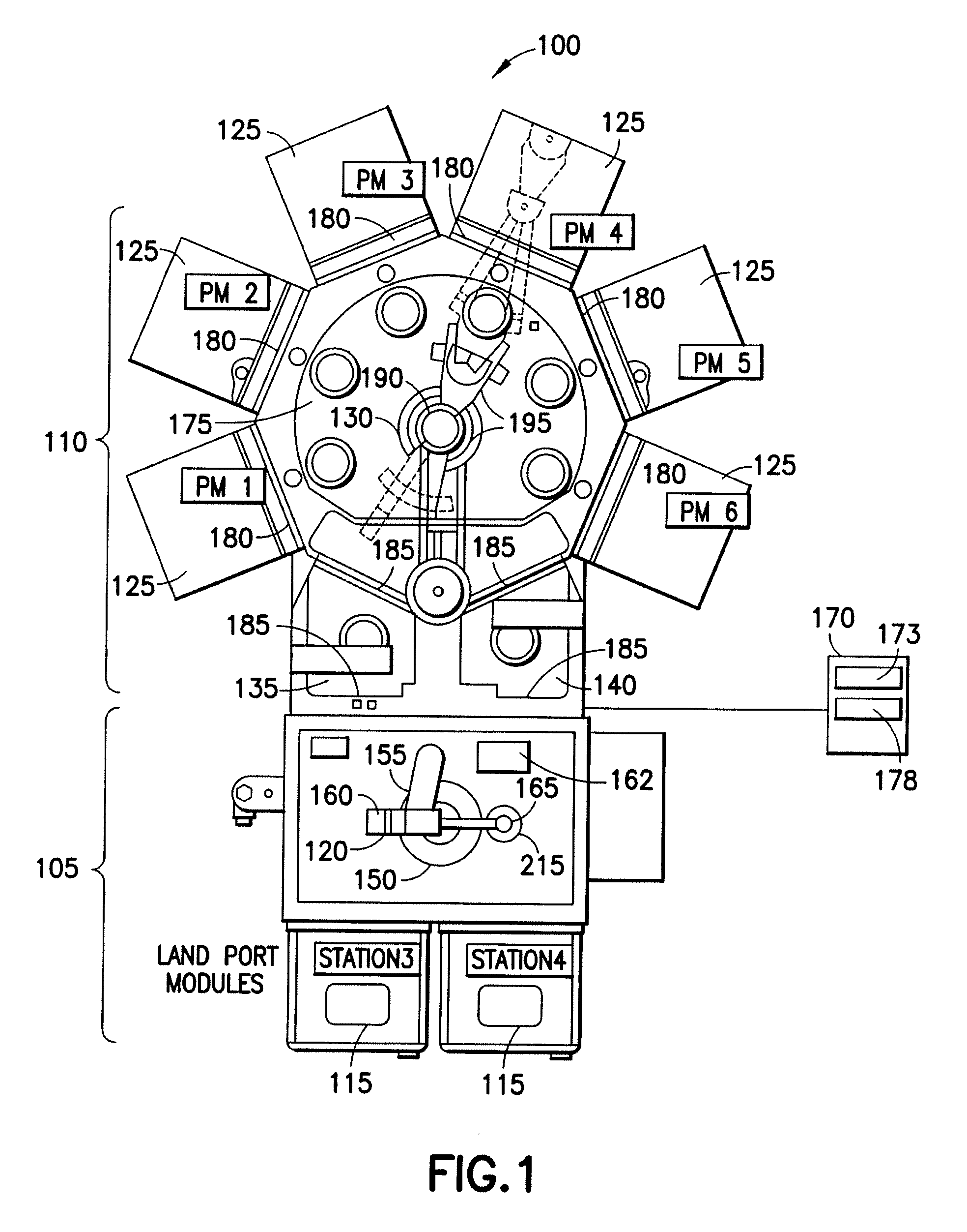
[0034]FIG. 1 illustrates a perspective view of a substrate processing apparatus 100 incorporating features of the exemplary embodiments. Although the embodiments disclosed will be described with reference to the embodiments shown in the drawings, it should be understood that the embodiments disclosed can be embodied in many alternate forms. In addition, any suitable size, shape or type of elements or materials could be used.

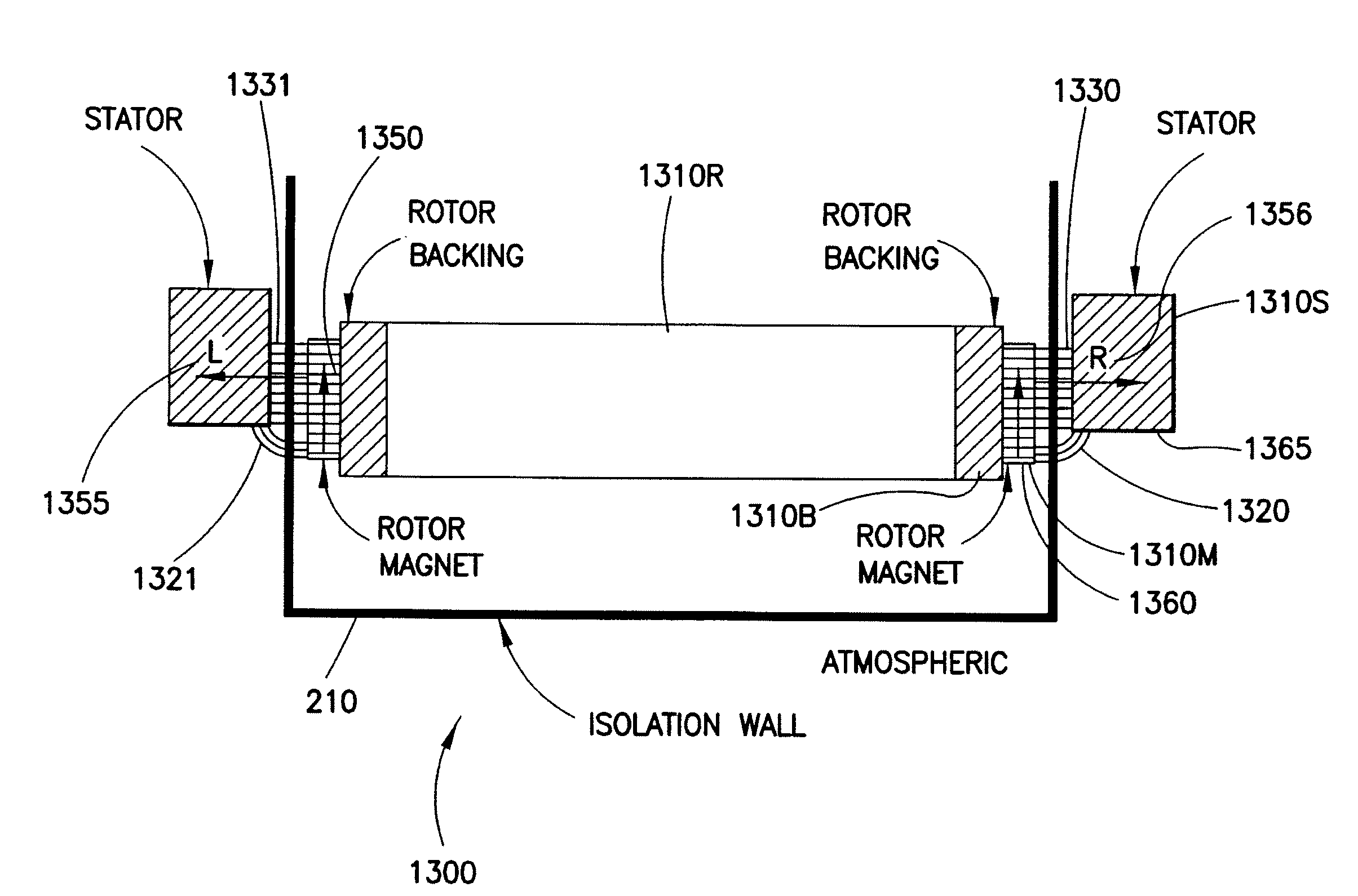
[0035]The exemplary embodiments may increase the reliability and cleanliness and vacuum performance of a robotic drive that may be used to, for example, transport substrates, align substrates, or perform any other suitable function in any suitable environment including, but not limited to, atmospheric, vacuum or controlled environments. The robotic drives of the exemplary embodiments may include windings configured to magnetically support the motor spindle and to manipulate the spindle such that the spindle can be translated in, for example, a horizontal plane...


PUM


Abstract

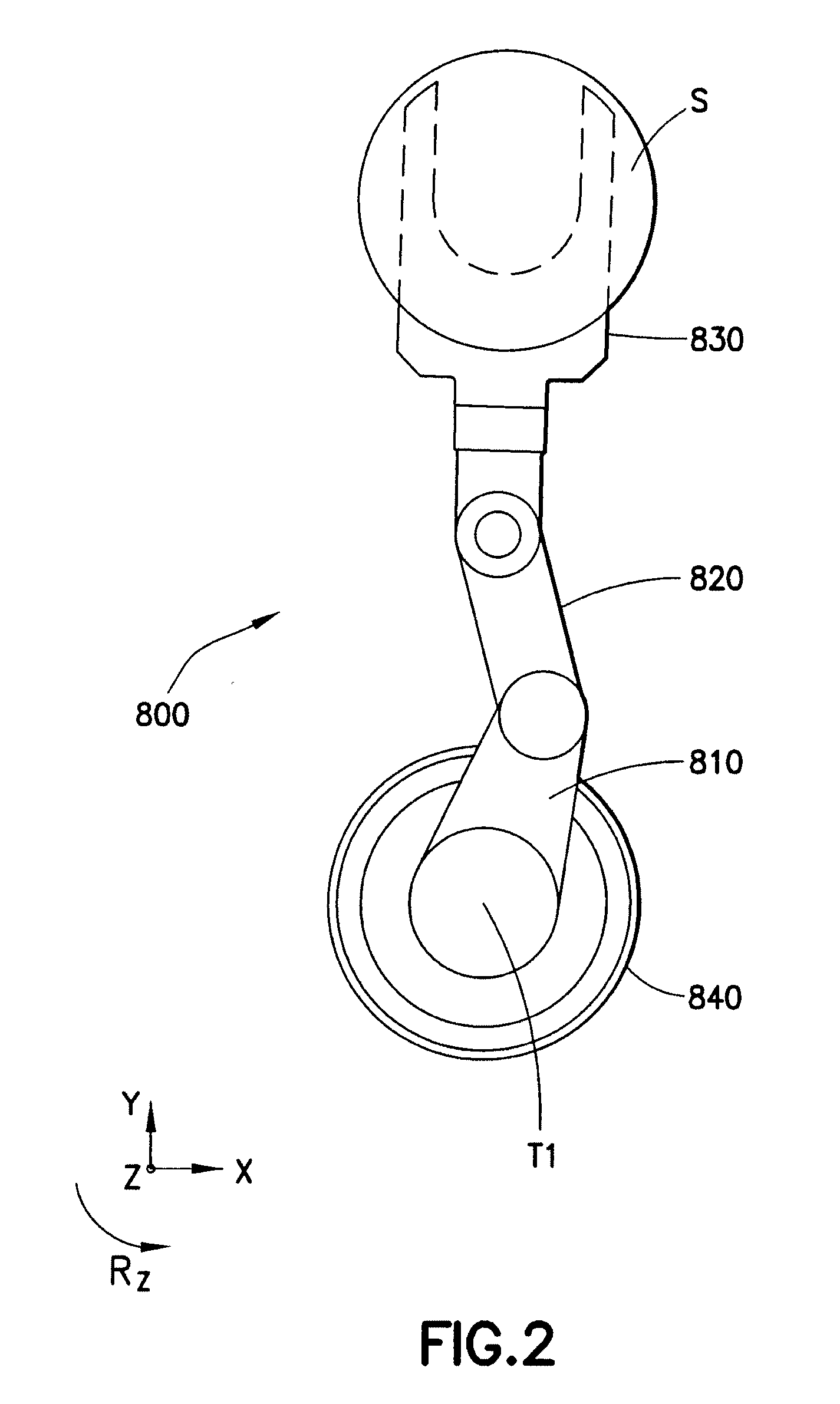
A drive section for a substrate transport arm including a frame, at least one stator mounted within the frame, the stator including a first motor section and at least one stator bearing section and a coaxial spindle magnetically supported substantially without contact by the at least one stator bearing section, where each drive shaft of the coaxial spindle includes a rotor, the rotor including a second motor section and at least one rotor bearing section configured to interface with the at least one stator bearing section, wherein the first motor section is configured to interface with the second motor section to effect rotation of the spindle about a predetermined axis and the at least one stator bearing section is configured to effect at least leveling of a substrate transport arm end effector connected to the coaxial spindle through an interaction with the at least one rotor bearing section.

Description

CROSS-REFERENCE TO RELATED APPLICATION(S)[0001]This application claims the benefit of U.S. Provisional Patent Application No. 60 / 946,687, filed on Jun. 27, 2007, the disclosure of which is incorporated by reference herein in its entirety.BACKGROUND[0002]1. Field[0003]The present embodiments relate to robot drives and, more particularly, to robot drives with magnetic bearings.[0004]2. Brief Description of Related Developments[0005]Conventional robotic drives such as for example, drives for use in a vacuum environment, utilize ball or roller bearings in the vacuum or other controlled environment to support drive shafts of the robotic drive. The bearings supporting the drive shafts may employ various lubricants to prevent metal fatigue and bearing failure. Specially formulate low vapor pressure greases are generally used to lubricate the robot drive bearings in the vacuum or controlled environment.[0006]However, the use of grease to lubricate the robot drive bearings is limited because...

Claims


Application Information

Patent Timeline
Patent Type & Authority Applications(United States)
IPC IPC(8): H02K7/09B25J17/00
CPCH02K7/09H02K29/03Y10T74/20305Y10T74/20317Y10T74/20329Y10S901/15Y10S901/23
Inventor GILCHRIST, ULYSSESHOSEK, MARTINMOURA, JAIRO TERRAKRISHNASAMY, JAYHOFMEISTER, CHRISTOPHER
Owner BOOKS AUTOMATION US LLC
Learn More